Injecting Bugs With An Electric Flyswatter

Hardware fault injection uses electrical manipulation of a digital circuit to intentionally introduce errors, which can be used to cause processors to behave in unpredictable ways. This unintentional behavior can be used to test for reliability, or it can be used for more nefarious purposes such as accessing code and data that was intended to be inaccessible. There are a few ways to accomplish this, and electromagnetic fault injection uses a localized electromagnetic pulse to flip bits inside a processor. The pulse induces a voltage in the processor’s circuits, causing bits to flip and often leading to unintentional behavior. The hardware to do this is very specialized, but [Pedro Javier] managed to hack a $4 electric flyswatter into an electromagnetic fault injection tool. (Page may be dead, try the Internet Archive version.)

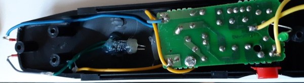
[Pedro] accomplishes this by turning an electric flyswatter into a spark-gap triggered EMP generator. He removes the business end of the flyswatter and replaces it with a hand-wound inductor in series with a small spark gap. Pressing the power button on the modified flyswatter charges up the output capacitor until the developed voltage is enough to ionize the air in the spark gap, at which point the capacitor discharges through the inductor. The size of the spark gap determines the charge that is built up—a larger gap results in a larger charge, which produces a larger pulse, which induces a larger voltage in the chip.

[Pedro] demonstrates how this can be used to produce arithmetic glitches and even induce an Arduino to dump its memory. Others have used electromagnetic fault injection to corrupt SRAM, and intentionally glitching the power supply pins can also be used to access otherwise protected data.

Extremely Simple Tesla Coil With Only 3 Components

Tesla Coils are a favourite here at Hackaday – just try searching through the archives, and see the number of results you get for all types of cool projects. [mircemk] adds to this list with his Extremely simple Tesla Coil with only 3 Components. But Be Warned — most Tesla coil designs can be dangerous and ought to be handled with care — and this one particularly so. It connects directly to the 220 V utility supply. If you touch any exposed, conductive part on the primary side, “Not only will it kill You, it will hurt the whole time you’re dying”. Making sure there is an ELCB in the supply line will ensure such an eventuality does not happen.

No prizes for guessing that the circuit is straight forward. It can be built with parts lying around the typical hacker den. Since the coil runs directly off 220 V, [mircemk] uses a pair of fluorescent lamp ballasts (chokes) to limit current flow. And if ballasts are hard to come by, you can use incandescent filament lamps instead. The function of the “spark gap” is done by either a modified door bell or a 220 V relay. This repeatedly charges the capacitor and connects it across the primary coil, setting up the resonant current flow between them. The rest of the parts are what you would expect to see in any Tesla coil. A high voltage rating capacitor and a few turns of heavy gauge copper wire form the primary LC oscillator tank circuit, while the secondary is about 1000 turns of thinner copper wire. Depending on the exact gauge of wires used, number of turns and the diameter of the coils, you may need to experiment with the value of the capacitor to obtain the most electrifying output.

If you have to look for one advantage of such a circuit, it’s that there is not much that can fail in terms of components, other than the doorbell / relay, making it a very robust, long lasting solution. If you’d rather build something less dangerous, do check out the huge collection of Tesla Coil projects that we have featured over the years.

Continue reading “Extremely Simple Tesla Coil With Only 3 Components”

This (mostly) Transparent Tesla Coil Shows It All

You’d be forgiven for assuming that a Tesla coil is some absurdly complex piece of high-voltage trickery. Clarke’s third law states that “any sufficiently advanced technology is indistinguishable from magic”, and lighting up a neon tube from across the room sure looks a lot like magic. But in his latest Plasma Channel video, [Jay Bowles] tries to set the record straight by demonstrating a see-through Tesla coil that leaves nothing to the imagination.

Of course, we haven’t yet mastered the technology required to produce transparent copper wire, so you can’t actually see through the primary and secondary coils themselves. But [Jay] did wind them on acrylic tubes to prove there aren’t any pixies hiding in there. The base of the coil is also made out of acrylic, which lets everyone see just how straightforward the whole thing is.

Beyond the coils, this build utilizes the DIY high-voltage power supply that [Jay] detailed a few months back. There’s also a bank of capacitors mounted to a small piece of acrylic, and a clever adjustable spark gap that’s made of little more than a few strategically placed pieces of copper pipe and an alligator clip. Beyond a few little details that might not be obvious at first glance, such as grounding the secondary coil to a layer of aluminum tape on the bottom of the base, it’s all right there in the open. No magic, just science.

[Jay] estimates this beauty can produce voltages in excess of 100,000 volts, and provides a demonstration of its capabilities in the video after the break. Unfortunately, before he could really put the new see-through coil through its paces, it took a tumble and was destroyed. A reminder that acrylic enclosures may be pretty, but they certainly aren’t invulnerable. With the value of hindsight, we’re sure the rebuilt version will be even better than the original.

If you’d rather not have your illusions shattered, we’ve seen plenty of complex Tesla coils to balance this one out. With witchcraft like PCB coils and SMD components, some of them still seem pretty magical.

Continue reading “This (mostly) Transparent Tesla Coil Shows It All”

Pour Yourself A Glass Of 100,000 Volts

You’d be hard pressed to find a hacker or maker who doesn’t have a soft spot for the tantalizing buzz and snap of a high voltage spark gap, but it remains the sort of project that most of us don’t take on personally. There’s a perceived complexity in building a device capable of shooting a proper spark through several inches of open air, with connotations of exotic components and massive hand-wound coils. Plus, nobody wants to inadvertently singe off their eyebrows.

While the latest video from [Jay Bowles] might not assuage anyone’s fear of performing impromptu electrolysis, it does at least prove that you don’t need to have a laboratory full of gear to produce six figure voltages. In fact, you don’t even need much in the way of electronics: the key components of this DIY Marx generator are made with little more than water and some household items.

This is made possible by the fact that the conductivity of water can be changed depending on what’s been dissolved into it. Straight tap water is a poor enough conductor that tubes of it can be used in place of high voltage resistors, while the addition of some salt and a plastic insulating layer makes for a rudimentary capacitor. You’ll still need wires to connect everything together and some bits of metal to serve as spark gaps, but nothing you won’t find lurking in the parts bin.

Of course, water and a smattering of nails won’t spontaneously generate electricity. You need to give it a bit of a kick start, and for that [Jay] is using a 15,000 volt DC flyback power supply that looks like it may have been built with components salvaged from an old CRT television. While the flyback transformer alone could certainly generate some impressive sparks, this largely liquid Marx generator multiplies the input voltage to produce a serious light show.

We’re always glad to see a new video from the perennially jovial [Jay] come our way. While his projects might not always be practical in the strictest sense, they never fail to inspire a lively discussion about the fascinating applications of high voltage.

Continue reading “Pour Yourself A Glass Of 100,000 Volts”

Raising The Titanic’s Radio Room

For some reason, of all the ships that have sailed the oceans, it’s the unlucky ones that capture our imagination. Few ships have been as unlucky as the RMS Titanic, sinking as she did on the night of April 15, 1912 after raking across an iceberg on her maiden voyage, and no ship has grabbed as much popular attention as she has.

During her brief life, Titanic was not only the most elegant ship afloat but also the most technologically advanced. She boasted the latest in propulsion and navigation technology and an innovation that had only recently available: a Marconi wireless room, used both for ship-to-shore and ship-to-ship communications.

The radio room of the Titanic landed on the ocean floor with the bow section of the great vessel. The 2.5-mile slow-motion free fall destroyed the structure of the room, but the gear survived relatively intact. And now, more than a century later, there’s an effort afoot to salvage that gear, with an eye toward perhaps restoring it to working condition. It’s a controversial plan, of course, but it is technologically intriguing, and it’s worth taking a look at what’s down there and why we should even bother after all these years.

Continue reading “Raising The Titanic’s Radio Room”

High Voltage Protects Low Denominations

How do you keep people out of your change jar? If you didn’t say with a 3D printed iris mechanism and high-voltage spark gap, then clearly you aren’t [Vije Miller]. Which is probably for the best, as we’re not sure we actually want to live in a world where there are two of these things.

Regular Hackaday readers will know that [Vije] has a way of using electromechanical trickery to inject a bit of excitement, and occasionally a little danger, into even the most mundane aspects of life. His latest project is an automated change jar that uses a pinpad to authenticate users, while everyone else gets the business end of a spark gap if the PIR sensor detects them getting to close.

You can see a demonstration of the jar in the video after the break, where he shows the jar’s ability to stop…himself, from getting access to it. Hey, nobody said it was meant to keep out real intruders. Though we do think a similar gadget could be a fun way to keep the kids out of the cookie jar before dinner, though we’d strongly suggest deleting the high-voltage component from the project before deploying it with a gullet full of Keebler’s best.

[Vije] was able to adapt a printable iris design he found on Thingiverse to fit over the mouth of the jar, and uses servos in the base to rotate the whole assembly around and open it up. The internal Arduino Nano handles reading from the pinpad, controlling the stepper, and of course firing up the spark generator for 1000 milliseconds each time the PIR sensor detects somebody trying to be cute. Just the sound of the arc should be enough to get somebody to reconsider the value of literal pocket change.

Some of the design elements used in this change jar’s high voltage components were influenced by the lessons learned when [Vije] was building his plasma-powered toilet air freshener. There’s a sentence we bet you never expected to read today.

Continue reading “High Voltage Protects Low Denominations”

3D Printing An Old-School Coherer

Coherers were devices used in some of the very earliest radio experiments in the 19th century. Consisting of a tube filled with metal filings with an electrode at each end, the coherer would begin to conduct when in the presence of radio frequency energy. Physically tapping the device would then loosen the filings again, and the device was once again ready to detect incoming signals. [hombremagnetico] has designed a basic 3D printed version of the device, and has been experimenting with it at home.

It’s a remarkably simple build, with the 3D printed components being a series of three brackets that combine to hold a small piece of plastic tube. This tube is filled with iron filings, and electrodes are inserted from either end. Super glue is used to seal the tube, and the coherer is complete.

The coherer can easily be tested by measuring the resistance between the two electrodes, and firing a piezo igniter near the tube. When the piezo igniter sparks, the coherer rapidly becomes conductive, and can be restored to a non-conductive state, or de-cohered, by tapping the tube.

Coherers and spark-gap sets are fun to experiment with, but be sure you have the proper approvals first. Video after the break.

Continue reading “3D Printing An Old-School Coherer”