Are We Not Indestructible? We Are Quiz Buttons!

In what we hope is a new trend in interviewing, some of the people at [Anthony]’s place of work asked him to make some wireless quiz buttons. He took the task quite seriously, making them extremely robust and low-power.

[Anthony] is experienced in the button arts, having made this party push button for a wedding reception. His design for the quiz buttons is a little different. Each button has an Arduino Pro mini and an nRF24L01 wireless RF module. On the receiver side is an Arduino Pro micro and an another RF module. A connected PC captures the serial data and  displays the pressed button’s ID. It also shows the order in which subsequent buttons were pressed and the time elapsed between them.

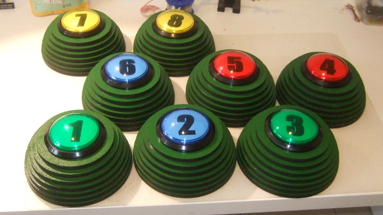
The really notable part of this build aside from the awesome laser-cut MDF Devo energy dome button housings is the extremely low power consumption of the transmitting Arduinos. [Anthony] has designed them to go into sleep mode which disables all on-board circuitry and only wakes on interrupt. He removed the power LED and the voltage regulator since they run on 2-AA batteries. The voltage regulator was drawing more than 25mA in sleep mode. Because of these mods, each button consumes < 1μA, which is less power than the batteries can self discharge over their lifetime.

[Thanks Jef]

Verifying A Wireless Protocol With RTLSDR

rtlsdr_nrf905_rtlizer

[Texane] is developing a system to monitor his garage door from his apartment. Being seven floors apart, running wires between the door and apartment wasn’t an option, so he turned to a wireless solution. Testing this wireless hardware in an apartment is no problem, but testing it in situ is a little more difficult. For that, he turned to software defined radio with an RTLSDR dongle.

The hardware for this project is based around a TI Stellaris board and a PTR8000 radio module. All the code for this project was written from scratch (Github here), making it questionable if the code worked on the first try. To test his code, [Texane] picked up one of those USB TV tuner dongles based around the RTL2832U chipset. This allowed him to monitor the frequencies around 433MHz for the packets his hardware should be sending.

After that, the only thing left to do was to write a frame decoder for his radio module. Luckily, the datasheet for the module made this task easy.

[Texane] has a frame decoder for the NRF905 radio module available in his Git. It’s not quite ready for serious applications, but for testing a simple radio link it’s more than enough.

[CNLohr] Demos His Photoetch PCB Process

etch

If you’re going to learn something, it only makes sense to learn from a master. [CNLohr] is known around these parts for his fablous PCBs, and he’s finally started to document his entire fabrication process.

[CNLohr] is using a photoetch process, where a mask is created with a laser printer on overhead transparencies. He covers the copper clad boards with a Riston photosensitive mask—available here, and they accept Bitcoin—sent through a laminator, and exposed with the laser printed mask and a UV grow bulb. After the mask has developed, [CNLohr] drops his boards into a ferric chloride bath that eats away the unexposed copper. He then removes the photomask with acetone and cuts the boards with a pair of aircraft snips, and they’re ready to be soldered up with components.

Yes, home PCB etching tutorials are pretty much a solved problem, but [CNLohr]’s work speaks for itself. He’s also the guy who made a microcontroller/Linux/Minecraft thing on a glass microscope slide. Learning from a guy with these skills means you’re learning from one of the best.

Video below, and there’s also a video going over the design of a PCB using KiCAD (!) and TopoR (!!!) available here.

Continue reading “[CNLohr] Demos His Photoetch PCB Process”

This SMD Reflow Hot Air Gun Hangs Around Your Workbench

smd_reflow_hot_air_gun_nc_80

Has reflowing surface mount components got you down? [Giorgos] is currently working on a project that will lift your spirits…. well at least your hot air gun. Tired of manually holding his heat gun in one hand and IR thermometer in the other, [Giorgos] set out to create a device to alleviate just that. Although not completed yet, it appears the machine’s intent is to hold the heat gun at an appropriate height above the work piece in order to achieve the correct reflow temperature. He doesn’t say how the height of the hot air gun will be controlled. We’d like to see a microcontroller adjust the height of the hot air gun depending on the temperature of the component to be reflowed. [Giorgos] gives an extremely detailed account of his build process. Make sure to check out all four pages of the project post!

We’ve seen a lot of interesting work from [Giorgos] over the years like this capacitive touch-pad entry system.

[via Dangerous Prototypes]

Hackaday Terms Of Use (aka: The Lawyers Are Coming!)

they-laywers-are-coming

Hackaday has posted Terms of Use and Privacy Policy documents which you should read. These can also be accessed through the Policies Page which is linked in the footer. We’ve edited this post to take up less room since it will be sticky for a few days. Original text and updates after the jump.

Continue reading “Hackaday Terms Of Use (aka: The Lawyers Are Coming!)”

FFT On The Raspi’s GPU

fft

The Raspberry Pi has been around for two years now, and still there’s little the hardware hacker can actually do with the integrated GPU. That just changed, as the Raspberry Pi foundation just announced a library for Fourier transforms using the GPU.

For those of you who haven’t yet taken your DSP course, fourier transforms take a function (or audio signal, radio signal, or what have you) and output the fundamental frequency. It’s damn useful for everything from software defined radios to guitar pedals, and the new GPU_FFT library is about ten times faster at this task than the Raspi’s CPU.

You can get a copy of  the GPU_FFT library by running rpi-update on your pi. If you happen to build anything interesting – something with a software defined radio or even a guitar pedal – you’re more than welcome to send it in to the Hackaday tips line. We’d love to see what you’re up to.

Paintball Picasso Purposely Misses Its Prey

waterlooPB

We’ve seen quite a few automated paintball marker systems over the years. Generally it’s the same story – a motion detection system used to target and fire upon the opposing team, prowlers, spouses, etc. [Waterloo Labs] decided to take a slightly different approach, and create a system that intentionally misses its target. Paintball Picasso uses a pair of Tippmann A-5 paintball markers to draw an outline around the person in its sights. This is a rather safe project for [Waterloo Labs], considering their previous adventures in car surfing.

The Paintball Picasso system uses a webcam to capture an image of a willing test subject. Picasso then processes the image. The human outline is plotted on a 50×50 grid of paintball pixels. Then the real fun begins. Paintball Picasso uses a National Instruments myRIO to command two paintball markers to simultaneously fire. The markers are fitted with high torque R/C style servos for pan and tilt. At 10 rounds per second the markers quickly draw the human outline. The test subject walks away slightly splattered, but otherwise unscathed. With a matrix of 2500 points, [Waterloo Labs] has enough resolution to draw some basic logos.

We liked the mounting system [Waterloo Labs] created for the markers. Using a mix of 3D printed parts, Lego Tetrix, 80/20 aluminum extrusion, and ball bearings, they fashioned a mount that moved smoothly enough for R/C servos to actuate, yet was strong enough to withstand the kick of firing. We’d love to see the servos swapped for stepper motors and belt drives. While open loop, stepper motors would afford more accuracy and a longer life than PWM driven R/C servos.

Continue reading “Paintball Picasso Purposely Misses Its Prey”