Photography Rig Captures Holy Grail Shots

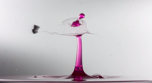
You’ve seen amazing shots of water spouts and milk crowns. You’ve seen shots of bullets piercing glass ornaments, playing cards, and poor, defenseless pieces of fruit. Maybe you’ve even seen that holy grail of shots—a bullet piercing a water spout. But how is it done? How do photographers capture this two-headed mythical beast of high-speed photography? [Maurice] has cracked the code and shared it for all to see.

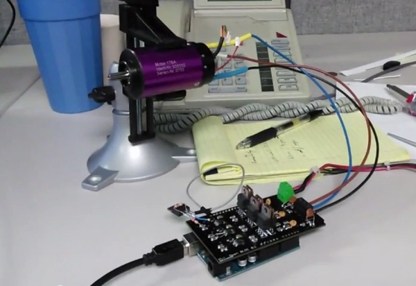
He uses a Camera Axe to trigger the camera, a device he came up with years ago that’s on its fifth version. His setup uses a 100mm macro lens, a key flash, and two fill flashes that sit behind a diffusing wall of whiteness. All three flashes are connected to a multi-flash board which feeds into Camera Axe. [Maurice] explains how he gets nice, tall water spouts by thickening it with xanthan gum. He adds Jet Dry to reduce the surface tension and some food coloring to keep things interesting.

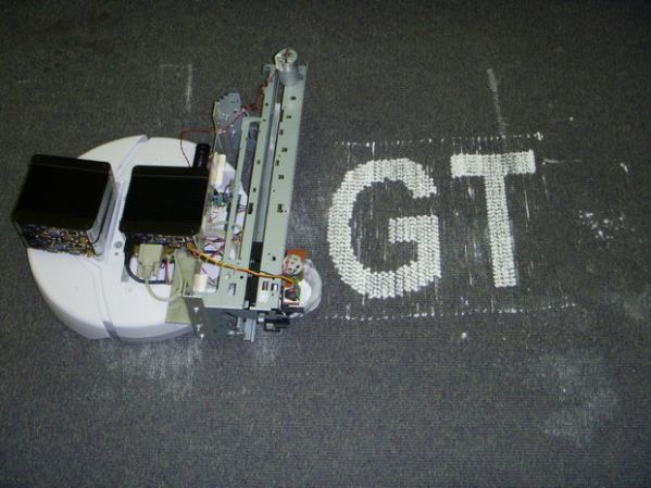
[Maurice] also runs through his pellet shooting rig, which he made with some polyethylene tubing and an air compressor. He ended up shooting the pellets at 20psi, which sends them traveling at 75 feet per second. They move slowly enough that he can use his own stomach to stop them in the demonstration. Dialing in just the right settings to get the pellet to intersect the spout at the right time took some finagling, and that will hold true for anyone who attempts to recreate this setup. He gives a link to his code files in the video description to get you started. Video is after the break.

Continue reading “Photography Rig Captures Holy Grail Shots”

Open-source BLDC motor driver

Brushless Motor Controller Shield For Arduino

Brushless motors are ubiquitous in RC applications and robotics, but are usually driven with low-cost motor controllers that have to be controlled with RC-style PWM signals and don’t allow for much customization. While there are a couple of open-source brushless drivers already available, [neuromancer2701] created his own brushless motor controller on an Arduino shield.

[neuromancer2701]’s shield is a sensorless design, which means it uses the back-EMF of the motor for feedback rather than hall effect sensors mounted on the motor. It may seem strange to leave those sensors unused but this allows for less expensive sensorless motors to work with the system. It also uses discrete FETs instead of integrated driver ICs, similar to other designs we have covered. Although he is still working on the back-EMF sensing in his firmware, the shield successfully drives a motor in open-loop mode.

The motor controller is commanded over the Arduino’s serial interface, and will support a serial interface to ROS (Robot Operating System) in the future. This shield could be a good alternative to hobby RC controllers for robots that need a customizable open-source motor controller. The PCB design and source code are available on GitHub.

Continue reading “Brushless Motor Controller Shield For Arduino”

Using A Standard Coil For NFC Tag Implant Reading

A few months ago Hackaday covered the xNT crowdfunding campaign which aimed at making an NTAG216 based NFC implant for different purposes. I actually backed it, found that standard NFC readers don’t perform well and therefore decided to try using a standard coil as an antenna for better reading performances.

Most NFC readers typically only have a small sweet spot where implant reading is possible. This is due to what we call coupling factor which depends on the reading distance and reader & NFC tag antenna geometries. Having a smaller antenna diameter increases the coupling factor and makes implant positioning easier.

In my detailed write-up you’ll find a good introduction to impedance matching, a process where a few passive components are added in series/parallel with an antenna to bring its complex impedance close to a RF signal transmitter’s. This usually requires expensive tools but allows optimal power transmission at a given frequency.

You may find our xNT coverage here.

Acoustic Impulse Marker Tracks Sounds With A Pencil

Acoustic Impulse Marker (aiming device)

Two students at Cornell University have put together a rather curious sound tracking device called an Acoustic Impulse Marker.

[Adam Wrobel] and [Michael Grisanti] study electrical and computer science, and for their final microcontroller class they decided to build this device using the venerable ATmega 1284p.

The system uses a three-microphone array to accurately position sharp noises within 5 degrees of accuracy. The microcontroller detects the “acoustic delay” between the microphones which allows it to identify the location of the sound’s source vector. It does this using an 8-stage analog system which converts the sounds from each microphone into a binary signal, which identifies when each microphone heard the noise. The resultant 3 binary signals are then compared for their time delay, it selects the two closest microphones, and then does a simple angle calculation based on the magnitudes of each to determine the sounds position. Continue reading “Acoustic Impulse Marker Tracks Sounds With A Pencil”

internal guitar effects

The Effects Are IN The Guitar? It’s So Simple…

We’ve all had that problem. Up on stage, rocking out Jimi Hendrix-style on guitar with your band, but frustrated at having to mess around with foot pedals to control all of the effects. [Richard] solved this problem in a unique way: he put a preamp and a microcontroller in a guitar that can create some very interesting effects.

For the musically challenged, electric guitars often have several sets of electromagnetic pickups that detect vibrations in the strings at different points along the strings. Selecting different pickup combinations with a built-in switch changes the sound that the guitar makes. [Richard] wired the pickups in his Fender Stratocaster to the microcontroller and programmed it to switch the pickups according to various patterns. The effect is somewhat like a chorus pedal at times and it sounds very unique.

The volume and tone knobs on the guitar are used to select the programmed patterns to switch various pickups at varying speeds. This has the added bonus of keeping the stock look of the guitar in tact, unlike some other guitars we’ve seen before. The Anubis preamp, as it is called, is a very well polished project and the code and wiring schematic are available on the project site along with some audio samples.

120 Node Rasperry Pi Cluster For Website Testing

[alexandros] works for resin.io, a website which plans to allow users to update firmware on embedded devices with a simple git push command. The first target devices will be Raspberry Pis running node.js applications. How does one perform alpha testing while standing up such a service? Apparently by building a monster tower of 120 Raspberry Pi computers with Adafruit 2.8″ PiTFT displays. We’ve seen some big Raspberry Pi clusters before, but this one may take the cake.

raspicluster2

The tower is made up of 5 hinged sections of plywood. Each section contains 24 Pis, two Ethernet switches and two USB hubs. The 5 sections can be run on separate networks, or as a single 120 node monster cluster. When the sections are closed in, they form a pentagon-shaped tower that reminds us of the classic Cray-1 supercomputer.

Rasberry Pi machines are low power, at least when compared to a desktop PC. A standard Raspi consumes less than 2 watts, though we’re sure the Adafruit screen adds to the consumption. Even with the screens, a single 750 watt ATX supply powers the entire system.

[alexandros] and the resin.io team still have a lot of testing to do, but they’re looking for ideas on what to do with their cluster once they’re done pushing firmware to it. Interested? Check out their Reddit thread!

PrintBot prints talcum powder on your floor

PrintBot Prints On The Ground, Uses Talcum Powder

Yes, this is a printing ‘bot but it’s not a 3D Printer. Even though it’s called Printbot, don’t get it confused with other products that may begin with ‘Print’ and end in ‘bot’. Printbot is half Roomba, half old inkjet print carriage drive and the remaining half is a small PC running Windows CE.

The whole point of this ‘bot is to draw/write/print things on the floor. No, not in ink, in talcum powder! The Roomba drives in one axis as the powder is systematically dropped in the ‘bots wake. It works one line at a time, similar to how a progressive scan TV displays an image on the screen. The PC on board the Printbot reads 8-bit gray scale images from a USB drive, re-samples the image and outputs the image one line at a time to an external microcontroller. The microcontroller is responsible for driving the Roomba forward as well as moving the hopper’s position and dispensing the powder in the correct place. Check out the small photo below. That black and white strip is not there for good looks. It is part of the encoder positioning system that is responsible for communicating the location of the hopper back to the microcontroller.

Continue reading “PrintBot Prints On The Ground, Uses Talcum Powder”