Voja’s EEPROM Emulator From 1991

We’re glad we’re not the only hacker-packrats out there! [Voja Antonic] recently stumbled on an EPROM emulator that he’d made way back in 1991. It’s a sweet build, so take your mind back 25 years if you can. Put on “Nevermind” and dig into a nicely done retro project.

The emulator is basically a PIC 16C54 microcontroller and some memory, with some buffers for input and output. On one side, it’s a plug-in replacement for an EPROM — the flash memory of a bygone era. On the other side, it connects via serial port to a PC. Instead of going through the tedious process of pulling the EPROM, erasing and reprogramming it, this device uploads new code in a jiffy.

722351466362213815

No need to emulate ancient EPROMS? You should still check out this build — the mechanics are great! We love the serial-port backplane that is soldered on at a 90° angle. The joint is a card-edge connector electrically, but also into a nice little box, reminiscent of [Voja]’s other FR4 fabrication tricks. The drilled hole with the LED poking out is classy. We’re never going to make an EPROM emulator, but we’re absolutely going to steal some of the fabrication techniques.

[Voja] is a Hackaday contributor, badge-designer, mad hacker, inspired clock-builder, and developer of (then) Yugoslavia’s first DIY PC.

The Politest Patent Discussion, OSHW V. Patents

We’ve covered [Vijay] refreshable braille display before. Reader, [zakqwy] pointed us to an interesting event that occured in the discussion of its Hackaday.io project page.

[Vijay] was inspired by the work of [Paul D’souza], who he met at Makerfaire Bangalore. [Paul] came up with a way to make a refreshable braille display using small pager motors. [Vijay] saw the light, and also felt that he could make the vibrating motor display in such a way that anyone could make it for themselves at a low cost.

Of course, [Paul], had patented his work, and in this case rightly so. As jaded as we have become with insane patent trolls, our expectation on receiving the tip was that [Paul] had sued [Vijay] out of house and home and kicked his dog while he was at it. A short google search shows that [Paul] is no patent troll, and is a leader in his field. He has done a lot to help the visually impaired with his research and inventions.

Instead we were greeted by a completely different conversation. [Paul] politely mentioned that his lawyer informed him that in order to protect his IP he needed to let [Vijay] know exactly how the information could be used. No cease and desist, in fact he encouraged [Vijay] to continue his open research as long as he made it clear that the methods described could not be used to make a marketable product without infringing on [Paul]’s patents. They’d need to get in touch with [Paul] and work something out before doing such.

[Vijay] responded very well to this information. His original goal was to produce a cheap braille display that could be made and sold by anyone. However, he did use [Paul]’s work as a basis for his variation. Since [Paul]’s commercial interests relied on his patent, there was a clear conflict, and it became obvious to [Vijay] that if he wanted to meet his goal he’d have to pick a new direction. So, he released his old designs as Creative Commons, since the CERN license he was using was invalidated by [Paul]’s patent. He made it very clear that anyone basing their work off those designs would have to get in touch with [Paul]. Undaunted by this, and still passionate about the project, [Vijay] has decided to start from scratch and see if he can invent an entirely new, unprotected mechanism.

Yes, the patent system is actually encouraging innovation by documenting prior work while protecting commercial and time investments of beneficial inventors. Well. That’s unexpected.

Kudos to [Paul] for encouraging the exploration of home hackers rather than playing the part of the evil patent owner we’ve all come to expect from these stories. Also [Vijay], for acting maturely to [Paul]’s polite request and not ceasing his work.

Hackaday Prize Entry: A Local Positioning System

Use of the global positioning system is all around us. From the satnav in your car to quadcopters hovering above a point, there are hundreds of ways we use the Global Positioning System every day. There are a few drawbacks to GPS: it takes a while to acquire a signal, GPS doesn’t work well indoors, and because nodes on the Internet of Things will be cheap, they probably won’t have a GPS receiver.

These facts open up the door for a new kind of positioning system. A local positioning system that uses hardware devices already have, but is still able to determine a location within a few feet. For his Hackaday Prize entry, [Blecky] is building the SubPos Ranger, a local positioning system based on 802.15.4 radios that still allows a device to determine its own location.

The SubPos Ranger is based on [Blecky]’s entry for the 2015 Hackaday Prize, SubPos that used WiFi, RSSI, and trilateration to determine a receiver’s position in reference to three or more base stations. It works remarkably well, even in places where GPS doesn’t, like parking garages and basements.

The SubPos Ranger is an extension of the WiFi-only SubPos, based on 802.15.4, and offers longer range and lower power than the WiFi-only SubPos system. It’s still capable of determining where a receiver is to within a few feet, making this the ideal solution for devices that need to know where are without relying on GPS.

The HackadayPrize2016 is Sponsored by:

Get Set For SAQ On Alexanderson Day With These Active Antennas

If you need to generate a radio frequency electrical signal, you will make some form of electronic oscillator. We’ll probably all be used to oscillators using transistors, tubes, logic gates or a host of other electronic technologies. Similarly if you need to generate radio frequencies at high powers, you’ll couple your oscillator to an amplifier, a relatively simple task with today’s electronic parts bin.

If you needed to do the same thing with a high power radio signal in the early years of the 20th century, none of these options were open to you. There were no transistors or integrated circuits, and the tubes of the day could not produce high power outputs. Radio engineers back then had to employ other solutions to the problem, one of which was the Alexanderson alternator. It’s old news we’ve covered here before at Hackaday, a high frequency alternator capable of generating hundreds of kilowatts in the VLF radio frequency range.

There is one operational Alexanderson alternator remaining in the world at the Varberg radio station at Grimeton in Sweden. It is no longer in constant use, but as a World Heritage Site and museum it is put on air a few times a year including the Sunday closest to the 2nd of July, known as Alexanderson Day. We come now to the point of this article: this year’s 3rd of July Alexanderson Day transmission is fast approaching, and since last time we covered it we signed off with a plea for a good VLF antenna design we should post a solution in good time to allow our readers to receive this year’s signal.

G3XBM's e-field VLF antenna
G3XBM’s e-field VLF antenna

Fixing up a receiver is easy enough, we linked to the original SAQrx VLF Receiver and the extended version in our previous coverage. Both pieces of software use your computer’s sound card as the front end of a software defined radio to receive the 17.2kHz from Grimeton. The antenna though presents a problem. You might think that attaching a long piece of wire to the microphone input would be enough, but the problem is that due to the huge wavelength of the VLF signal any reasonable long wire you might be able to assemble simply wouldn’t be long enough to deliver a good result. Clearly a different antenna is required, and the solution comes courtesy of a high-impedance active e-field antenna. This uses a FET input and a surprisingly small patch antenna to deliver a low noise floor at VLF frequencies rather than to be the amplifier you might expect.

We’ve found a couple of designs for you to look at. The first is a two transistor version you will find in various different guises on many sites. This one uses an MPF102 FET, but you should be able to substitute a J310. The second design is a little more surprising, while it is the same idea of a FET input amplifier it uses a TL071 op-amp as its active device. This is in no way an IC you’d normally expect to find in an RF circuit, however the frequency in question is not that of your normal RF.

If you build either of these antennas we hope you’ll be able to hear the Alexanderson Day transmission. The point of a high power VLF transmitter is that it has a huge coverage area, so it should be possible to receive it across all of Europe and perhaps into the eastern United States. If you are out of range though, never fear. You can always try to pick it up through a handy webSDR receiver closer to the source.

Alexanderson alternator picture By Gunther Tschuch (Own work) [ CC BY 2.5 ], via Wikimedia Commons.


Hackaday Links Column Banner

Hackaday Links: June 26, 2016

Solar Freaking Roadways. What is it? It’s technology that replaces all roadways with a smooth sheet of glass and solar panels. You know how asphalt is soooo easy to repair and soooooo cheap? Yes, this is the exact opposite of that. They’re coming to freaking Missouri. A parking lot for the Route 66 Welcome Center in Conway, MO will be paved with the solar freaking roadways that netted $2 Million in an Indiegogo campaign two years ago.

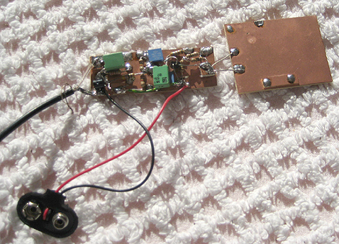
There is a National Potato Expo. As far as I can tell, this is a trade show for potatoes and potato-related paraphernalia. As with all trade shows you need a great demo, in this case one involving potatoes. How about a phone charging station powered by potatoes? It’s a bunch of potatoes, copper pipe, galvanized nails (neat design, btw), and a USB socket. Yes, it works, but not well.

The travelling hacker box is a USPS flat rate box filled to the brim with random bits and bobs of electronics, shipped back and forth between dozens of electron enthusiasts. It’s making one last trip around the US, and now the travelling hacker box needs destinations from Idaho to Michigan. Idaho, of course, is a fictional state created in 2004 for Napoleon Dynamite, but that still leaves Montana, the Dakotas, Wisconsin, Minnesota, and the UP. If you live in one of these states, there’s a travelling hacker box with your name on it. Request to join the project and PM me on hackaday.io.

It’s election year in the US, and that means half of the population hates one candidate, half of the population hates another candidate, and half of the population will vote. Don’t think about that for too long. Here’s an Arduino doing something topical with Twitter.

Hotends for 3D printers are getting more and more robust, but thermistors are fiddly little things. E3D just came up with the solution. It’s a standard, modular temperature ‘cartridge’ that fits in E3D’s heater blocks. You can already change out the heater cartridge on a 3D printer for a higher wattage model, and now you can change out a thermistor for a thermocouple just as easily. E3D sells their stuff in GBP, so considering recent events it might be a good time to pick up a new hotend for that Monoprice 3D printer you picked up

The 8-Bit Generation recently released their documentary The Commodore Warschronicling the stupendous rise and meteoric fall of Commodore. Now they’re working on the Atari version and they’re funding it with a Kickstarter. Rumor has it Hackaday’s own [Bil Herd] has been asked to narrate.

Here’s another Hackaday Retro Edition success story @KetturiFox pulled up the Hackaday Retro Edition on a Texas Instruments TravelMate 5000 laptop. That’s a relatively modern laptop with a 75MHz Pentium, PCMCIA slots, and a nub mouse.

“I Can Reflow” Merit Badge

[Nick Sayer] can reflow, and he can prove it. He designed a simple blinking-LED circuit that uses SMD parts to, well, blink LEDs. That’s not the point, though. It’s designed to be a test platform for reflow soldering, and to use a minimum number of valuable parts. Plus, it says “I can reflow!” in exposed copper. What else do you want?

OK, as far as “proving it” goes, the badge isn’t 100% reliable — we hand-solder 0805 components all day long. But still, if you want to try your hand at reflowing a circuit board, and you don’t want to ruin a lot of expensive parts if you fail, something like this is a good idea.

The design is open, and it’s really the idea that’s the point here anyway. How about something that would be really onerous to hand-solder, but still cheap? We’re thinking a matrix of tiny LEDs and a shift register or something.

We just ran an article on a hand-soldering challenge board, this seems the perfect complement. Display both proudly on your desk and confound and amaze your coworkers!

Homemade Smart Glasses Shows Why Smart Glasses Are Hard

[Harris Shallcross] decided to build a pair of smart glasses and recently completed a first prototype of his project ‘Ochi’ – an STM32 based, BLE-connected, OLED eyeglass display. There are of course several homebrew smart glasses projects out there; many are more polished-looking and nearly all of them also display information from a smartphone over Bluetooth. This one is interesting partly because it highlights many of the design challenges that smart glasses and other near-eye displays face. It also demonstrates the iterative development process: begin by getting something working to learn what does and doesn’t cut it at a basic level, and don’t optimize prematurely; let the process bring problems to the surface.

Ochi-1 Smart Glasses BBC feed Square
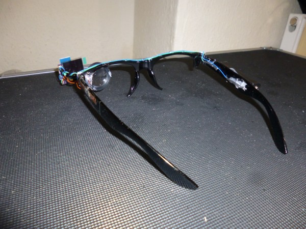
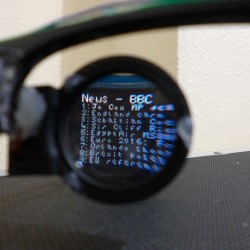
For his project, [Harris Shallcross] used a small 0.95″ diagonal 96×64 color OLED as the display. The lens is from a knockoff Google Cardboard headset, and is held in a 3D printed piece that slides along a wire rail to adjust focus. The display uses a custom font and is driven by an STM32 microcontroller on a small custom PCB, with an HM11 BLE module to receive data wirelessly. Power is provided by a rechargeable lithium-ion battery with a boost converter. An Android app handles sending small packets of data over Bluetooth for display. The prototype software handles display of time and date, calendar, BBC news feed, or weather information.

Devices like these have a lot to deal with. Weight and distribution of that weight is a concern, the size and comfort of the optics is important, and displaying data on a small OLED is only part of the battle – choosing what information to display and when are vital to the device being actually useful in any way, otherwise it’s just a tech demo.

This project set out to show whether it was possible to use the parts listed to make a glasses mounted smart display that was at least somewhat functional, and the software to support it. Clearly, [Harris Shallcross] succeeded at that, but what really showcases the development process is his list of improvements – what he decided needs to go into a second version, and why. One of those goals is to improve the optics; perhaps there’s something to learn from The $60 Bluetooth Head Mounted Display project, which used a similar OLED and a prism to locate the display off to the side instead of in front.