Measuring Sharpie Thickness… The Ink Itself, Not The Pen!

How we missed this one from a few years ago is unknown, but we’re glad to catch up with it now. Have you ever needed to measure how thick the ink in a Sharpie line is? Of course you haven’t. But if you needed to, how would you do it? Using a wicked-sensitive indicator gauge and levering an interesting test setup.
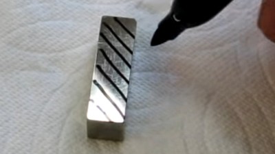
[Tom] from [oxtoolco] got his hands on a tool that measures in 1/10,000,000th (that’s one ten-millionth) increments and was wondering what kind of shenanigans you can do with this Lamborghini of dial indicators. It’s one thing to say you’re going to measure ink, but coming up with the method is the leap. In this case it’s a gauge block — a piece of precision ground metal with precise dimensions and perfectly perpendicular faces. By zeroing the indicator on the block, then adding lines from the Sharpie and measuring again, you can deduce the thickness of the ink markings.

After arraying diagonal lines on the gauge block it is placed lines-down under the dial indicator. This distributes the ink layer across a larger area, as probing the ink line directly would likely result in inaccurate readings. On that topic the gauge block is moved using pliers, as introducing heat from your fingers could result in expansion of the metal upsetting the readings.

The results? Black, blue, and red Sharpie were all tested, alongside blue and black Dykem layout fluid. Ten samples of each were run and the readings were all very close, save a couple of obvious outliers. Clocking in the thinnest is black Sharpie at about 118 millionths of an inch (~30 microns) and blue Dykem was the thickest at 314 millionths (86 microns). [Tom] quips that since we now know the thickness, you could even use ink as a shim.

If you can’t get enough Sharpie in your life, try it as an extremely satisfying add-on for your plasma cutter.

Continue reading “Measuring Sharpie Thickness… The Ink Itself, Not The Pen!”

Inputs Of Interest: The Differently Dexterous DataHand Directionalizes Digits

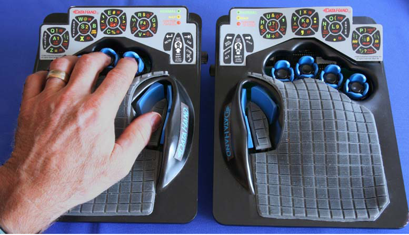
If you had debilitating pain from repetitive stress injury in the 1990s, there were a lot of alternative keyboard options out there. One of the more eye-catching offerings was the DataHand keyboard made by DataHand Systems out of Phoenix, AZ. The DataHand debuted in 1993 with a price tag around $2,000. While this is admittedly pretty steep for the average consumer, it was well within the IT budgets of companies that wanted to avoid workman’s comp claims and keep their employees typing away.

In theory, this is holy grail territory for anti-RSI keyboards. The DataHand was designed to eliminate wrist motion altogether by essentially assigning a d-pad plus a regular push-down button to each finger. The layout resembles QWERTY as closely as possible and uses layers to access numbers, symbols, and other functions, like a rudimentary mouse.

Although if you put them this close together, you’re kind of missing the point. Image via Bill Buxton

Ergonomic to the Max

Typing on the DataHand is supposed to be next to effortless. The directional switches are all optical, which probably has a lot to do with the eye-popping price point. But instead of being spring-loaded, these switches use magnets to return to the neutral position.

Continue reading “Inputs Of Interest: The Differently Dexterous DataHand Directionalizes Digits”

Test Unknown Fuses Without Destroying Them

There’s a problem with fuses. On the face of it, testing would seem to be a one-shot deal — exceed the rated current and see if it blows. But once you know the answer, the device is useless. If only there were a way to test fuses without damaging them.

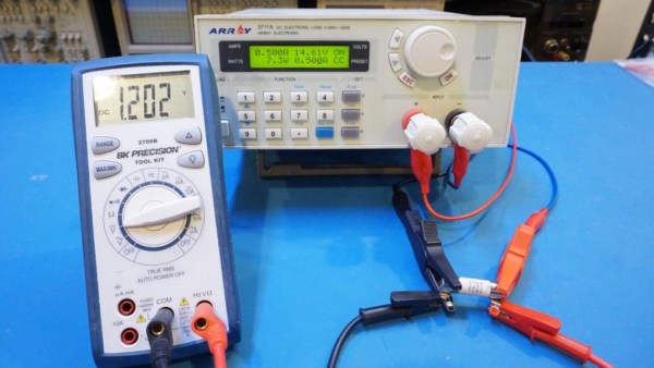
As it turns out there is, and [Kerry Wong] weaves quite a tale about his attempts to non-destructively test fuses. The fuses in question are nothing fancy — just the standard glass tube type, from a cheap assortment kit off Amazon. Therein lies the problem: can such cheap devices be trusted? Finding out requires diving much deeper into the technology of fuses than many people will have done, including understanding how the thermal and electrical characteristics of the fuse element behave.

[Kerry]’s test setup is simple, consisting of a constant current power supply and a voltmeter across the fuse to measure the voltage drop caused by the resistance of the fuse element. As he ramps up the current, the voltage drop increases linearly due to the increase in resistance of the alloy with increasing temperature. That only lasts up to a point, where the fuse resistance starts increasing exponentially. Pushing much past the point where the resistance has doubled would blow the fuse, so that’s the endpoint of his tests. Perhaps unsurprisingly, his no-name fuses all went significantly beyond their rated current, proving that you get what you pay for. See the video below for the tests and an analysis of the results.

It’s handy to know there’s a way to check fuses without popping them, and we’ll file this one away for future reference. Don’t forget that you should always check the fuse when troubleshooting, because you never know what the last person did to it.

Continue reading “Test Unknown Fuses Without Destroying Them”

Roll Your Own Automation With ESPHome

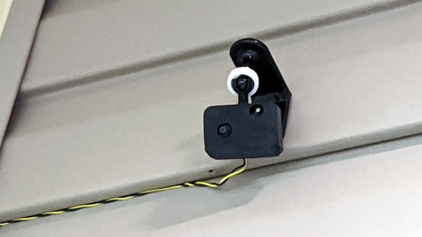
There are several different paths to a smart home, and [Marcus] eventually settled on using ESPHome and ESP8266/ESP32 based devices to create a complete DIY smart home solution which covers his garage door, sprinklers, LED strips, light bulbs, and outlets. There’s even an experimental (and very economical) ESP32-CAM based camera, shown here.

In fact, [Marcus]’s write-up could double as a sort of reference design. If you’re curious about ESPHome, be sure to read what he has to say because he explains exactly how he configured each device and any challenges he encountered in the process.

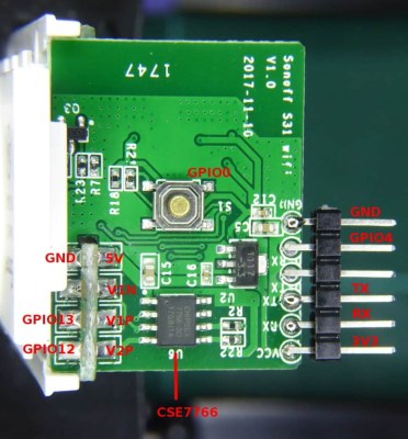
Beyond the software guidance, the post is also a great resource on how to flash a new firmware onto several different smart devices. [Marcus] provides nicely labeled images of the boards that show where you need to connect your programmer, which just might save you some trouble down the line. Though he did manage to set fire to one of the bulbs, so keep an eye out for that.

Tasmota is another open source option for controlling ESP8266-based devices, and if you’d like to explore that direction don’t forget that flashing Sonoff devices with Tasmota firmware recently got much, much easier.