Check Your Clip Leads

[Matthias] bought cheap clip leads online and, wisely, decided to check them. We’ve had the same experience that he’s had. Sometimes, these cheap leads are crimped and don’t make good contact. However, you can usually solder them and completely fix them. Not this time, however, as you can see in the video below.

The resistance for the leads was a bit on the high side, which is usually a sure sign of this problem. But soldering didn’t really make a big difference. A homemade clip lead, for example, read under 20 milliohms, but a test lead from the new batch read about 260 milliohms even after being soldered.

Continue reading “Check Your Clip Leads”

LEAF Mission Seeks To Grow Plants On The Moon

Space Lab's LEAF model crops & growth chamber.
Credit: Space Lab

We have seen a recent surge of interest in whether it’s possible to grow potatoes and other plants in Martian soil, but what is the likelihood that a future (manned) lunar base could do something similar? To that end [Space Lab] is developing the LEAF project that will be part of NASA’s upcoming Artemis III lunar mission. This mission would be the first to have Americans return to the Moon by about 2028, using the somewhat convoluted multi-system SLS-Starship-Lunar Gateway trifecta. The LEAF (Lunar Effects on Agricultural Flora) science module will feature three types of plants (rape (Brassica Rapa), duckweed and cress (Arabidopsis thaliana) ) in an isolated atmosphere.

The main goal of this project is to find out how the plants are affected by the lunar gravity, radiation and light levels at the landing site at the south pole. This would be the equivalent of a hydroponics setup in a lunar base. After about a week of lunar surface time the growth chamber will be split up into two: one returning back to Earth for examination and the other remains on the surface to observe their long-term health until they perish from cold or other causes.

This is not the first time that growing plants on the lunar surface has been attempted, with China’s Chang’e 4 mission from 2019. The lander’s Lunar Micro Ecosystem featured a range of seeds as well, which reportedly successfully sprouted, but the project was terminated after 9 days instead of the planned 100 due to issues with heating the biosphere during the brutal -52°C lunar night. Hopefully LEAF can avoid this kind of scenario when it eventually is deployed on the Moon.

Clever Circuit Makes Exercise Slightly Less Boring

We say this with the greatest respect, but [Joel] — your exercise routine is horrible! Kudos for getting up and doing something, but 108 trips up and down the stairs? That sounds like torture, not exercise. Even [Joel] admits that it’s so boring that he loses count, and while we’d bet that he isn’t likely to restart the routine when that happens, it’s still annoying enough that he built this clever little lap counter to automate the task.

We kid, of course; any exercise is better than no exercise, and the stairs offer few excuses for skipping the daily workout. To bust the boredom problem, [Joel] toyed with a couple of ideas for toting up his laps before landing on a beam-break optical system with sensors at the top and the bottom of the stairs. Worried about the potential for false triggering by swinging arms and legs, he searched for ideas for bounceless switch circuits in the old “Engineer’s Notebook” by [Forrest Mims] and found a circuit close enough to modify for his needs. Each sensor setup has a high-output red LED and a phototransistor on one side of the stairwell, and a retroreflector on the opposite wall. Breaking the beam switches off the LED on that sensor and switches the other one on, to save on battery power.

The sensor’s flips and flops are counted and displayed on a three-digit seven-segment LED; [Joel] offers no detail on the counter itself, but with [Mims] as his muse, we suspect it’s something like the three-digit BCD counter circuit a few pages on from the bounceless switch circuit. The lap counter is shown in action in the brief video below.

Continue reading “Clever Circuit Makes Exercise Slightly Less Boring”

Rapid Prototyping PCBs With The Circuit Graver

Walking around the alley at Hackaday Supercon 2024, we noticed an interesting project was getting quite a bit of attention, so we got nearer for a close-up. The ‘Circuit Graver’ by [Zach Fredin] is an unconventional PCB milling machine, utilizing many 3D printed parts, the familiar bed-slinger style Cartesian bot layout and a unique cutting head. The cutting tool, which started life as a tungsten carbide lathe tool, is held on a rotary (‘R’) axis but can also move vertically via a flexure-loaded carriage driven by a 13 kg servo motor.

The stocky flexure took a lot of iteration, as the build logs will show. Despite a wild goose chase attempting to measure the cutting force, a complete machine solution was found by simply making everything stiff enough to prevent the tool from chattering across the surface of the FR4 blank. Controlling and maintaining the rake angle was a critical parameter here. [Zach] actually took an additional step, which we likely wouldn’t have thought of, to have some copper blanks pre-fabricated to the required size and finished with an ENIG coating. It’s definitely a smart move!
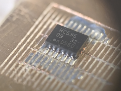
To allow the production of PCB-class feature sizes compatible with a traditional PCB router, the cutting tool was sharpened to a much smaller point than would be used in a lathe using a stone. This reduced the point size sufficiently to allow feature sizes down to 4 mils, or at least that’s what initial characterization implied was viable.  As you can see from the build logs, [Zach] has achieved a repeatable enough process to allow building a simple circuit using an SMT 74HC595 and some 0402 LEDs to create an SAO for this year’s Supercon badge. Neat stuff!

We see a fair few PCB mills, some 3D printed, and some not. Here’s a nice one that fits in that former category. Milling PCBs is quite a good solution for the rapid prototyping of electronics. Here’s a guide about that.

Continue reading “Rapid Prototyping PCBs With The Circuit Graver”

FLOSS Weekly Episode 808: Curl – Gotta Download ’em All

This week, Jonathan Bennett and Randal Schwartz chat with Daniel Stenberg about curl! How many curl installs are there?! What’s the deal with CVEs? How has curl managed to not break its ABI for 18 years straight? And how did Daniel turn all this into a career instead of just a hobby? Watch to find out!

Continue reading “FLOSS Weekly Episode 808: Curl – Gotta Download ’em All”

Supercon 2023: Restoring The Apollo Guidance Computer

Humans first visited the Moon in 1969.  The last time we went was 1972, over 50 years ago. Back then, astronauts in the Apollo program made their journeys in spacecraft that relied on remarkably basic electronics that are totally unsophisticated compared to what you might find in an expensive blender or fridge these days. Core among them was the Apollo Guidance Computer, charged with keeping the craft on target as it travelled to its destination and back again.

Marc Verdiell, also known as CuriousMarc, is a bit of a dab hand at restoring old vintage electronics. Thus, when it came time to restore one of these rare and storied guidance computers, he was ready and willing to take on the task. Even better, he came to the 2023 Hackaday Supercon to tell us how it all went down!

Continue reading “Supercon 2023: Restoring The Apollo Guidance Computer”

Hardware-in-the-Loop Continuous Integration

How can you tell if your software is doing what it’s supposed to? Write some tests and run them every time you change anything. But what if you’re making hardware? [deqing] has your back with the Automatic Hardware Testing rig. And just as you’d expect in the software-only world, you can fire off the system every time you update the firmware in your GitHub.

A Raspberry Pi compiles the firmware in question and flashes the device under test. The cool part is the custom rig that simulates button presses and reads the resulting values out. No actual LEDs are blinked, but the test rig looks for voltages on the appropriate pins, and a test passes when the timing is between 0.95 and 1.05 seconds for the highs and lows. Firing this entire procedure off at every git check-in ensures that all the example code is working.

So far, we can only see how the test rig would work with easily simulated peripherals. If your real application involved speaking to a DAC over I2C, for instance, you’d probably want to integrate that into the test rig, but the principle would be the same.

Are any of you doing this kind of mock-up hardware testing on your projects? Is sounds like it could catch bad mistakes before they got out of the house.