Repairing A BPS-305 30V Bench Power Supply

When [Tahmid Mahbub] recently reached for his ‘Lavolta’ BPS-305 bench supply, he was dismayed to find that despite it being a 30V, 5A-rated unit, the supply refused to output more than 15V. To be fair, he wasn’t sure that he had ever tried to push it beyond 15V in the years that he had owned it, but it had better live up to its specs. Ergo out came the screwdriver to open the power supply to see what had broken, and hopefully to fix it.

After some more probing around, he discovered that the unit had many more issues, including a highly unstable output voltage and output current measurement was completely wrong. Fortunately this bench power supply turns out to be very much like any number of similar 30V, 5A units, with repair videos and schematics available.

While [Tahmid] doesn’t detail his troubleshooting process, he does mention the culprits: two broken potentiometers (VR104 and VR102). VR104 is a 5 kOhm pot in the output voltage feedback circuit and VR102 (500 Ohm) sets the maximum output current. With no 500 Ohm pot at hand, a 5 kOhm one was combined with a 470 Ohm resistor to still allow for trimming. Also adjusted were the voltage and current trimpots for the front display as they were quite a bit off. Following some testing on the reassembled unit, this power supply is now back in service, for the cost of two potentiometers and a bit of time.

Experimental setup and measured optical depth. (Credit: Josiah Sinclair et al,, PRX Quantum, 2022)

Quantum Mechanics And Negative Time With Photon-Atom Interactions

Within our comfortable world of causality we expect that reactions always follow an action and not vice versa. This why the recent chatter in the media about researchers having discovered ‘negative time’ with photons being emitted before the sample being hit by source photons created such a stir. Did these researchers truly just crack our fundamental concepts of (quantum) physics wide open? As it turns out, not really.

Much of the confusion stems from the fact that photons aren’t little marbles that bounce around the place, but are an expression of (electromagnetic) energy. This means that their resulting interaction with matter (i.e. groupings of atoms) is significantly more complicated, often resulting in the photonic energy getting absorbed by an atom, boosting the energy state of its electron(s) before possibly being re-emitted as the excited electrons decay into a lower orbit.

This dwell time before re-emission is what is confusing to many, as in our classical understanding we’d expect this to be a very deterministic process, while in a quantum world it most decidedly is not.

Continue reading “Quantum Mechanics And Negative Time With Photon-Atom Interactions”

A Foil Tweeter, Sound From Kitchen Consumables

The world of audio has produced a variety of different loudspeaker designs over the last century, though it’s fair to say that the trusty moving coil reigns supreme. That hasn’t stopped plenty of engineers from trying new ways to make sound though, and [R.U.H] is here with a home-made version of one of them. It’s a foil tweeter, a design in which a corrugated strip of foil is held in a magnetic field, and vibrates when an audio frequency current is passed through it.

He shows a couple of takes on the design, both with neodymium magnets but with different foils and 3D printed or wooden surrounds. They both make a noise when plugged into an amplifier, and unsurprisingly the thicker foil has less of the high notes.

We can see that in there is the possibility for a high quality tweeter, but we can’t help having one concern. This device has an extremely low impedance compared to the amplifier, and thus would probably be drawing far too much current. We’d expect it to be driven through a transformer instead, if he had any care for not killing the amplifier.

Happily there are other uses for a ribbon, they are far better known as microphones.

Continue reading “A Foil Tweeter, Sound From Kitchen Consumables”

An animated GIF of Engineer Bo's Precision Bluetooth Scroll Wheel wirelessly, and effortlessly scrolling down the Hack A Day blog with a single finger

Doomscroll Precisely, And Wirelessly

Around here, we love it when someone identifies a need and creates their own solution. In this case, [Engineer Bo] was tired of endless and imprecise scrolling with a mouse wheel. No off-the-shelf solutions were found, and other DIY projects either just used hacked mice scroll wheels, customer electronics with low-res hardware encoders, or featured high-res encoders that were down-sampled to low-resolution. A custom build was clearly required.

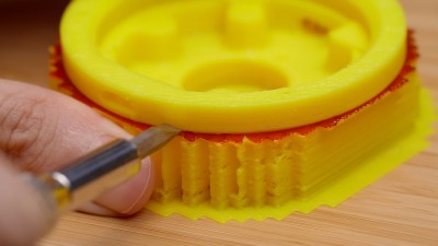
A photo of a 3D printed yellow plastic form with red marker drawn on the top of the support material and used in Engineer Bo's Precision Bluetooth Scroll Wheel

We loved seeing hacks along the whole process by [Engineer Bo], working with components on hand, pairing sensors to microcontrollers to HID settings, 3D printing forms to test ergonomics, and finishing the prototype device. When 3D printing, [Engineer Bo] inserted a pause after support material to allow drawing a layer of permanent marker ink that acts as a release agent that can later be cleaned with rubbing alcohol. 

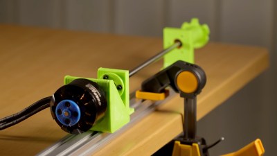
We also liked the detail of a single hole inside used to install each of the three screws that secure the knob to the base. While a chisel and UV-curing resin cleaned up some larger issues with the print, more finishing was required. For a project within a project, [Engineer Bo] then threw together a mini lathe with 3D printed and RC parts to make sanding easy.

Scroll down with your clunky device to see the video that illustrates the precision with a graphic of a 0.09° rotation and is filled with hacky nuggets. See how the electronics were selected and the circuit designed and programmed, the use of PCBWay’s CNC machining in addition to board assembly services, and how to deal with bearings that spin too freely. [Engineer Bo] teases that a future version might use a larger bearing for less wobble and an anti-slip coating on the base. Will the board files and 3D models be released, too? Will these be sold as finished products or kits? Will those unused LED drivers be utilized in an upcoming version? We can’t wait to see what’s next for this project.

Continue reading “Doomscroll Precisely, And Wirelessly”

Sony Vaio Revived: Power, The Second 80%

A bit ago, I’ve told you about how the Sony Vaio motherboard replacement started, and all the tricks I used to make it succeed on the first try. How do you plan out the board, what are good things to keep in mind while you’re sourcing parts, and how do you ensure you finish the design? This time, I want to tell you my insights about what it takes for your new board revision to stay on your desk until completion, whether it’s helping it not burn up, or making sure the bringup process is doable.

Uninterrupted, Granular Power

Power was generally comfortable to design, but I did have to keep some power budgets in mind. A good exercise for safeguarding your regulators is keeping a .txt file where you log consumers and their expected current consumption on each board power rail, making sure all of your power regulators, connectors, and tracks, can handle quite a bit more than that current. Guideline: increase current by 20%-50% when figuring out the specs for switching regulators and inductors, and, multiply by 10-20% when figuring out conversion losses going between downstream and upstream rails.

I did have a blunder in this department – not accounting for track current early on enough. I laid out the board using 0.5mm wide tracks for power – it looked spacious enough. Then, I put “0.5mm” into a track current calculator and saw a harrowing temperature increase for the currents I was expecting. At that point in routing, it took some time to shift tracks around to accomodate the trace width I actually needed, which is to say, I should’ve calculated it all way way earlier. Thankfully, things went well in the end.

Continue reading “Sony Vaio Revived: Power, The Second 80%”

Why 2025 Will Not Be The Year Of Linux On The Desktop

One of the longest running jokes in our sphere is that the coming year will finally be the year of “Linux on the Desktop.” Never mind that the erosion of the traditional Windows-style desktop form of computing is a thing, or that Linux-derived operating systems such as Android or Chrome OS are running on literally billions of devices across the globe, it sends up the unreasonable optimism of Linux enthusiasts back in the day that their nascent platform could depose Windows from its pedestal.

If there’s one thing we like more than a good tech joke then, it’s a well-written tech rant, and [Artem S. Tashkinov] has penned a doozy in Why Linux is not ready for the desktop, the final edition“. It’s Linux trolling at its finest, and will surely get many a crusty open source devotee rushing to their keyboard to decry its ideas.

Aside from the inherent humor then, reading it we have to admit that he makes a set of very cogent points. Even having used a Linux desktop exclusively for a very long time indeed there’s no shame in admitting that it’s not perfect, and things such as the mildly annoying state of network file sharing or the complexity for most users of getting to grips with the security model are very fair criticisms. And the last section on the Linux community hits hard, it’s necessary to admit that the world of open source doesn’t always welcome people trying to use its software as well as it could.

But as power users of a Linux desktop for everything, more than just for writing Hackaday, we’d take the view that for all its undoubted faults, it still offers a better experience than the latest version of Windows. Oddly it could now be an acceptable desktop for many people, but the sad thing is that the need for that may well have passed to those Android and Chrome OS devices we mentioned earlier.

We’ve been known to have our own Linux related rants from time to time.

New Years Circuit Challenge: Make This RFID Circuit

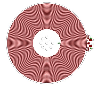
A 125kHz PCB antenna, a spiral pattern on a PCB.
The Proxmark3 PCB 125kHz antenna., GNU GPL version 2, GitHub link.

Picture this: It’s the end of the year, and a few hardy souls gather in a hackerspace to enjoy a bit of seasonal food and hang out. Conversation turns to the Flipper Zero, and aspects of its design, and one of the parts we end up talking about is its built-in 125 kHz RFID reader.

It’s a surprisingly complex circuit with a lot of filter components and a mild mystery surrounding the use of a GPIO to pulse the receive side of its detector through a capacitor. One thing led to another as we figured out how it worked, and as part of the jolity we ended up with one member making a simple RFID reader on the bench.

Just a signal generator making a 125 kHz square wave, coupled to a two transistor buffer pumping a tuned circuit. The tuned circuit is the coil scavenged from an old RFID card, and the capacitor is picked for resonance in roughly the right place. We were rewarded with the serial bitstream overlaying the carrier on our ‘scope, and had we added a filter and a comparator we could have resolved it with a microcontroller. My apologies, probably due to a few festive beers I failed to capture a picture of this momentous event. Continue reading “New Years Circuit Challenge: Make This RFID Circuit”