What does one do when frustrated at the lack of affordable, open source portable trackers? If you’re [OG-star-tech], you design your own and give it modular features that rival commercial offerings while you’re at it.
What’s a star tracker? It’s a method of determining position based on visible stars, but when it comes to astrophotography the term refers to a sort of hardware-assisted camera holder that helps one capture stable long-exposure images. This is done by moving the camera in such a way as to cancel out the effects of the Earth’s rotation. The result is long-exposure photographs without the stars smearing themselves across the image.
Interested? Learn more about the design by casting an eye over the bill of materials at the GitHub repository, browsing the 3D-printable parts, and maybe check out the assembly guide. If you like what you see, [OG-star-tech] says you should be able to build your own very affordably if you don’t mind 3D printing parts in ASA or ABS. Prefer to buy a kit or an assembled unit? [OG-star-tech] offers them for sale.
Frustration with commercial offerings (or lack thereof) is a powerful motive to design something or contribute to an existing project, and if it leads to more people enjoying taking photos of the night sky and all the wonderful things in it, so much the better.
Every few years or so, a development in computing results in a sea change and a need for specialized workers to take advantage of the new technology. Whether that’s COBOL in the 60s and 70s, HTML in the 90s, or SQL in the past decade or so, there’s always something new to learn in the computing world. The introduction of graphics processing units (GPUs) for general-purpose computing is perhaps the most important recent development for computing, and if you want to develop some new Python skills to take advantage of the modern technology take a look at this introduction to CUDA which allows developers to use Nvidia GPUs for general-purpose computing.
Of course CUDA is a proprietary platform and requires one of Nvidia’s supported graphics cards to run, but assuming that barrier to entry is met it’s not too much more effort to use it for non-graphics tasks. The guide takes a closer look at the open-source library PyTorch which allows a Python developer to quickly get up-to-speed with the features of CUDA that make it so appealing to researchers and developers in artificial intelligence, machine learning, big data, and other frontiers in computer science. The guide describes how threads are created, how they travel along within the GPU and work together with other threads, how memory can be managed both on the CPU and GPU, creating CUDA kernels, and managing everything else involved largely through the lens of Python.
Getting started with something like this is almost a requirement to stay relevant in the fast-paced realm of computer science, as machine learning has taken center stage with almost everything related to computers these days. It’s worth noting that strictly speaking, an Nvidia GPU is not required for GPU programming like this; AMD has a GPU computing platform called ROCm but despite it being open-source is still behind Nvidia in adoption rates and arguably in performance as well. Some other learning tools for GPU programming we’ve seen in the past include this puzzle-based tool which illustrates some of the specific problems GPUs excel at.
[Martin] of [Wintergatan] is on a quest to create the ultimate human-powered, modern marble music machine. His fearless mechanical exploration and engineering work, combined with considerable musical talent, has been an ongoing delight as he continually refines his designs. We’d like to highlight this older video in which he demonstrates how to dynamically regulate the speed of a human-cranked music machine by taking inspiration from gramophones: he uses a flyball governor (or centrifugal governor).
The faster the shaft turns, the harder the disk brake is applied.
These devices are a type of mechanical feedback system that was invented back in the 17th century but really took off once applied to steam engines. Here’s how they work: weights are connected to a shaft with a hinged assembly. The faster the shaft spins, the more the weights move outward due to centrifugal force. This movement is used to trigger some regulatory action, creating a feedback loop. In a steam engine, the regulator adjusts a valve which keeps the engine within a certain speed range. In a gramophone it works a wee bit differently, and this is the system [Wintergatan] uses.
To help keep the speed of his music machine within a certain narrow range, instead of turning a valve the flyball governor moves a large disk brake. The faster the shaft spins, the harder the brake is applied. Watch it in action in the video (embedded below) which shows [Wintergatan]’s prototype, demonstrating how effective it is.
[Wintergatan]’s marble machine started out great and has only gotten better over the years, with [Martin] tirelessly documenting his improvements on everything. After all, when every note is the product of multiple physical processes that must synchronize flawlessly, it makes sense to spend time doing things like designing the best method of dropping balls.
One final note: if you are the type of person to find yourself interested and engaged by these sorts of systems and their relation to obtaining better results and tighter tolerances, we have a great book recommendation for you.
Although a somewhat common feature on cars these days, tire pressure sensors (TPS) are also useful on bicycles. The SKS Airspy range of TPS products is one such example, which enables remote monitoring of the air pressure either to a special smartphone app (SKS MYBIKE) or to a Garmin device. Of course, proprietary solutions like this require reverse-engineering to liberate the hardware from nasty proprietary firmware limitations, which is exactly what [bitmeal] did with a custom firmware project.
Rather than the proprietary and closed communication protocol, the goal was to use the open ANT+ sensor instead, specifically the (non-certified) TPS profile which is supported by a range of cycling computers. Before this could happen the Airspy TPS hardware had to be first reverse-engineered so that new firmware could be developed and flashed. These devices use the nRF52832 IC, meaning that development tools are freely available. Flashing the custom firmware requires gaining access to the SWD interface, which will very likely void the warranty on a $160 – 240 device.
The SWD programmer is then attached to the 1.27 mm spaced SWD holes per the instructions on the GitHub page. After flashing the provided .hex file you can then connect to the TPS as an ANT+ device, but instructions are also provided for developing your own firmware.
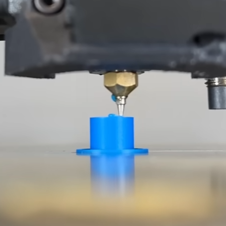
[JanTec Engineering] was fascinated by the idea of using a 3D printer’s hot end to inject voids and channels in the infill with molten plastic, leading to stronger prints without the need to insert hardware or anything else. Inspiration came from two similar ideas: z-pinning which creates hollow vertical channels that act as reinforcements when filled with molten plastic by the hot end, and VoxelFill (patented by AIM3D) which does the same, but with cavities that are not uniform for better strength in different directions. Craving details? You can read the paper on z-pinning, and watch VoxelFill in (simulated) action or browse the VoxelFill patent.
With a prominent disclaimer that his independent experiments are not a copy of VoxelFill nor are they performing or implying patent infringement, [JanTec] goes on to use a lot of custom G-code (and suffers many messy failures) to perform some experiments and share what he learned.
Using an airbrush nozzle as a nozzle extension gains about 4 mm of extra reach.
One big finding is that one can’t simply have an empty cylinder inside the print and expect to fill it all up in one go. Molten plastic begins to cool immediately after leaving a 3D printer’s nozzle, and won’t make it very far down a deep hole before it cools and hardens. One needs to fill a cavity periodically rather than all in one go. And it’s better to fill it from the bottom-up rather than from the top-down.
He got better performance by modifying his 3D printer’s hot end with an airbrush nozzle, which gave about 4 mm of extra length to work with. This extra long nozzle could reach down further into cavities, and fill them from the bottom-up for better results. Performing the infill injection at higher temperatures helped fill the cavities more fully, as well.
Another thing learned is that dumping a lot of molten plastic into a 3D print risks deforming the print because the injected infill brings a lot of heat with it. This can be mitigated by printing the object with more perimeters and a denser infill so that there’s more mass to deal with the added heat, but it’s still a bit of a trouble point.
[JanTec] put his testing hardware to use and found that parts with infill injection were noticeably more impact resistant than without. But when it came to stiffness, an infill injected part resisted bending only a little better than a part without, probably because the test part is very short and the filled cavities can’t really shine in that configuration.
These are just preliminary results, but got him thinking there are maybe there are possibilities with injecting materials other than the one being used to print the object itself. Would a part resist bending more if it were infill injected with carbon-fibre filament? We hope he does some follow-up experiments; we’d love to see the results.
You wake up in the morning, and check Hackaday over breakfast. Then it’s off to work or school, where you’ve already had to explain the Jolly Wrencher to your shoulder-surfing colleagues. And then to a hackspace or back to your home lab, stopping by the skull-and-cross-wrenches while commuting, naturally. You don’t bleed red, but rather #F3BF10. It’s time we talked.
The Hackaday writing crew goes to great lengths to cover all that is interesting to engineers and enthusiasts. We find ourselves stretched a bit thin and it’s time to ask for help. Want to lend a hand while making some extra dough to plow back into your projects? We’re looking for contributors to write a few articles per week and keep the Hackaday flame burning.
Contributors are hired as private contractors and paid for each article. You should have the technical expertise to understand the projects you write about, and a passion for the wide range of topics we feature. You’ll have access to the Hackaday Tips Line, and we count on your judgement to help us find the juicy nuggets that you’d want to share with your hacker friends.
One example article written in the voice of Hackaday. Include a banner image, between 150 and 300 words, the link to the project, and any in-links to related and relevant Hackaday features. We need to know that you can write.
Details about your background (education, employment, interests) that make you a valuable addition to the team. What do you like, and what do you do?
Links to your blog/project posts/etc. that have been published on the Internet, if any.
Questions? Don’t hesitate to ask below. Ladies and Gentlemen, start your applications!
At least that’s what [Frost Sheridan] did with a vintage Kodak MegaPlus 4.2i, a camera that was aimed at the industrial and scientific market at a time when everyone was still using film for snapshots. Making this workhorse ride again meant diving into the manual, luckily still available after all these years, and figuring out what pins on the 68 pin connector would be useful. [Frost] worked out the pins for serial commands plus the 10-bit parallel interface, although he settled for the eight most significant bits to make things simpler. A Teensy with some extra RAM and a serial interface chip takes care of sending commands to the camera and pulling pixels off the parallel interface, and a 128×160 LCD provides a much-needed viewfinder.
With a battery pack mounted the whole thing is reasonably portable, if a bit of a chore to use. It’s worth the effort, though; the picture quality is fantastic, with a wide dynamic range and plenty of contrast. Hats off to [Frost] for bringing this beauty back to life without making any permanent modifications to it.