The weaving is on the left, a microphoto of the chip die is on the right.

The 555 As You’ve Never Seen It: In Textile!

The Diné (aka Navajo) people have been using their weaving as trade goods at least since European contact, and probably long before. They’ve never shied from adopting innovation: churro sheep from the Spanish in the 17th century, aniline dies in the 19th, and in the 20th and 21st… integrated circuits? At least one Navajo Weaver, [Marilou Schultz] thinks they’re a good match for the traditional geometric forms. Her latest creation is a woven depiction of the venerable 555 timer.

“Popular Chip” by Marilou Schultz. Photo courtesy of First American Art Magazine, via righto.com

This isn’t the first time [Marilou] has turned an IC into a Navajo rug; she’s been weaving chip rugs since 1994– including a Pentium rug commissioned by Intel that hangs in USA’s National Gallery of Art–but it’s somehow flown below the Hackaday radar until now. The closest thing we’ve seen on these pages was a beaded bracelet embedding a QR code, inspired by traditional Native American forms.

That’s why we’re so thankful to [VivCocoa] for the tip. It’s a wild and wonderful world out there, and we can’t cover all of it without you. Are there any other fusions of tradition and high-tech we’ve been missing out on? Send us a tip.

2025 One Hertz Challenge: 555 Timer Gets A Signal From Above

One of the categories we chose for the One Hertz Challenge is “Could Have Used a 555.” What about when you couldn’t have, but did anyway? The 555 is famously easy to use, but not exactly the most accurate timer out there — one “ticking” at 1 Hz will pulse just about once per second (probably to within a millisecond, depending on the rest of the circuit), but when you need more precise timing, the 555 just won’t cut it. Not on its own, anyway.

An Allan deviation plot
Allan Deviation can be a bit confusing, but generally — lower is more accurate

This entry by [burble] shows us how the humble 555 can hold its own in more demanding systems with some help from a GPS receiver. He used the One Pulse per Second (1PPS) output from a GPS module to discipline the 1 Hz output from a 555 by modulating the control voltage with a microcontroller.

Okay, this sounds a bit like baking a cake by buying a cake, scraping all the icing off, then icing it yourself, but what better way to learn how to ice a cake? The GPS-disciplined 555 is way more accurate than a free running one — just check out that Allan Deviation plot. While the accuracy of the standard 555 begins to decrease as oscillator drift dominates, the GPS-disciplined version just keeps getting better (up to a point — it would also eventually begin to increase, if the data were recorded for long enough). Compared to other high-end oscillators though, [burble] describes the project’s accuracy in one word: “Badly.”

That’s okay though — it really is a fantastic investigation into how GPS-disciplined oscillators work, and does a fantastic job illustrating the accuracy of different types of clocks, and some possible sources of error. This project is a great addition to some of the other precision timekeeping projects we’ve seen here at Hackaday, and a very fitting entry to the competition. Think you can do better? Or much, much worse? You’ve got a few weeks left to enter!

2025 One Hertz Challenge: A 555, But Not As We Know It

We did explicitly ask for projects that use a 555 timer for the One Hertz Challenge, but we weren’t expecting the 555 to be the project. Yet, here we are, with [matt venn]’s Open Source 1Hz Blinky, that blinks a light with a 555 timer… but not one you’d get from Digikey. 

Hooking a 555 to blink an LED at one hertz is a bog-simple, first-electronics-project type of exercise, unless you have to make the 555 first. Rather than go big, as we have seen before, [matt venn] goes very small, with a 555 implemented on a tiny sliver of Tiny Tapeout 6.

We’ve covered projects using that tapeout before, but in case you missed it, Tiny Tapeout gives space to anyone to produce ASICs on custom silicon using an open Process Design Kit, and we have [matt venn] to thank for it. The Tiny Tapeout implementation of the 555 was actually designed by [Vincent Fusco].

Of course wiring it up is a bit more complicated than dropping in a 555 timer to the circuit: the Tiny Tapeout ASIC must be configured to use that specific project using its web interface.  There’s a demo video embedded below, with some info about the project– it’s not just a blinking LED, so it’s worth seeing. The output isn’t exactly One Hertz, so it might not get the nod in the Timelord category, but it’s going to be a very strong competitor for other 555-based projects– of which we could really use more, hint-hint. You’ve got until August 19th, if you think you can use a 555 to do something more interesting than blink an LED.

Continue reading “2025 One Hertz Challenge: A 555, But Not As We Know It”

The 555 Writ Large

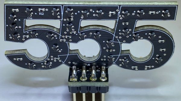
Few electronic ICs can claim to be as famous as the 555 timer. Maybe part of the reason is that the IC doesn’t have a specific function. It has a lot of building blocks that you can use to create timers and many other kinds of circuits. Now [Stoppi] has decided to make a 555 out of discrete components. The resulting IC, as you can see in the video below, won’t win any prizes for diminutive size. But it is fun to see all the circuitry laid bare at the macro level.

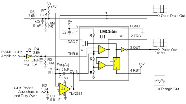
The reality is that the chip doesn’t have much inside. There’s a transistor to discharge the external capacitor, a current source, two comparators, and an RS flip flop. All the hundreds of circuits you can build with those rely on how they are wired together along with a few external components.

Even on [stoppi]’s page, you can find how to wire the device to be monostable, stable, or generate tones. You can also find circuits to do several time delays. A versatile chip now blown up as big as you are likely to ever need it.

Practical? Probably not, unless you need a 555 with some kind of custom modification. But for understanding the 555, there’s not much like it.

We’ve seen macro 555s before. It is amazing how many things you can do with a 555. Seriously.

Continue reading “The 555 Writ Large”

Stylus Synth Should Have Used A 555– And Did!

For all that “should have used a 555” is a bit of a meme around here, there’s some truth to it. The humble 555 is a wonderful tool in the right hands. That’s why it’s wonderful to see this all-analog stylus synth project by EE student [DarcyJ] bringing the 555 out for the new generation.

The project is heavily inspired by the vintage stylophone, but has some neat tweaks. A capacitor bank means multiple octaves are available, and using a ladder of trim pots instead of fixed resistors makes every note tunable. [Darcy] of course included the vibrato function of the original, but no, he did not use a 555 for that, too. He used an RC oscillator. He put a trim pot on that, too, to control the depth of vibrato, which we don’t recall seeing on the original stylophone.

The writeup is very high quality and could be recommended to anyone just getting started in analog (or analogue) electronics– not only does [Darcy] explain his design process, he also shows his pratfalls and mistakes, like in the various revisions he went through before discovering the push-pull amplifier that ultimately powers the speaker.

Since each circuit is separately laid out and indicated on the PCB [Darcy] designed in KiCad for this project. Between that and everything being thru-hole, it seems like [Darcy] has the makings of a lovely training kit. If you’re interested in rolling your own, the files are on GitHub under a CERN-OHL-S v2 license,  and don’t forget to check out the demo video embedded below to hear it in action.

Of course, making music on the 555 is hardly a new hack. We’ve seen everything from accordions to paper-tape player pianos to squonkboxes over the years. Got another use for the 555? Let us know about it, in the inevitable shill for our tip line you all knew was coming. Continue reading “Stylus Synth Should Have Used A 555– And Did!”

The Magic Touch: A 555 Touch Switch

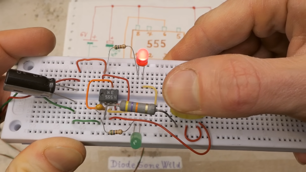
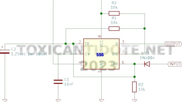
There seems to be nothing a 555 can’t do. We’ve seen it before, but [electronzapdotcom] reminds us you can use a 555 and a few parts to make a reasonable touch switch in this video, embedded below.

The circuit uses some very large resistors so that noise from your body can overcome the logic level on the trigger and threshold inputs. You can easily adapt this idea if you need a simple touch switch. Though we imagine this circuit wouldn’t work well if you were in a quiet environment. We suspect 50 or 60 Hz hum is coupling through your finger and triggering the pins, but it could be a different effect.

How reliable is it? Beats us. The circuit is a bistable, so essentially your finger pumps a signal into a flip-flop. This is old trick, but could be useful. Of course, if you really need a touch switch, you have plenty of options. You can get little modules. Or, directly measure skin resistance.

Continue reading “The Magic Touch: A 555 Touch Switch”

Chase Light SAO Shouldn’t Have Used A 555, And Didn’t

Around these parts, projects needlessly using a microcontroller where a simpler design would do are often derided with the catch-all “Should have used a 555,” even if the venerable timer chip wouldn’t have been the ideal solution. But the sentiment stands that a solution more complicated than it needs to be is probably one that needs rethinking, as this completely mechanical chaser light badge Simple Add-On (SAO) aptly demonstrates.

Rather than choosing any number of circuits to turn a strip of discrete lights on and off, [Johannes] took inspiration for his chaser lights from factory automation mechanisms that move parts between levels on steps that move out of phase with each other, similar to the marble-raising mechanism used in [Wintergatan]’s Marble Machine X.

Two thin plates with notches around the edge are sandwiched together inside the 3D printed case of the SAO, between the face and the light source. A small motor and a series of gears rotate the two masks 180° out of phase with each other, which creates the illusion that the light is moving.

It’s pretty convincing; when we first saw the video below, we were sure it was a row of tiny LEDs around the edge of the badge.

Hats off to [Johannes] for coming up with such a clever mechanism and getting it working just in time for Hackaday Europe. If you need to catch up on the talks, we’ve got a playlist ready for you.

Continue reading “Chase Light SAO Shouldn’t Have Used A 555, And Didn’t”