Here’s a clever hack. Simple, elegant, and eminently cost-effective: using an SMD capacitor to hold your flash media in place!
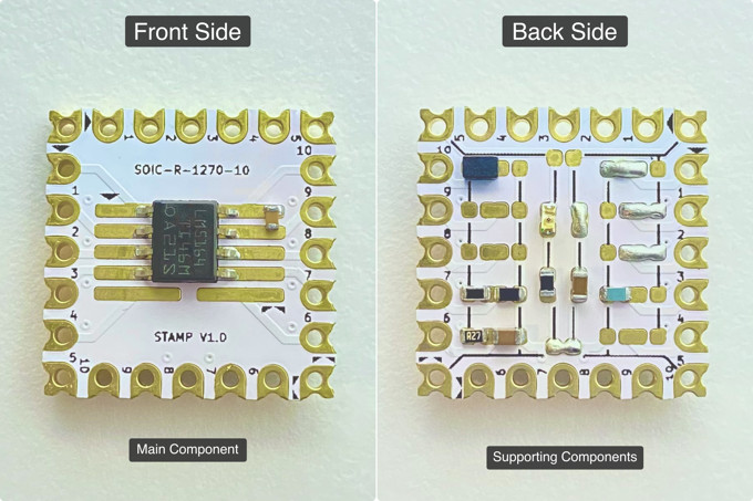
This is a hack that can pretty much be summed up with just the image at the top of the page — a carefully placed SMD capacitor soldered to a routed tab makes for an extremely cost effective locking mechanism for the nearby SD card slot. There’s just enough flexibility to easily move the capacitor when its time to insert or eject your media.
It’s worth noting that the capacitor in this example doesn’t even appear to be electrically connected to anything. But there’s also no reason you couldn’t position one of the capacitors in your existing bill of materials (BOM). This form of mechanical support will be much cheaper than special purpose clips or mounts. Not a big deal for low-volume projects, but if you’re going high-volume this is definitely something to keep in mind.
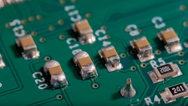
If you’re just getting started with SMD capacitors then one of the first things to learn is how to solder them. Also, if you’re hoping to salvage them then try to look for newer equipment which is more likely to have SMD components than through-hole. If you’re planning to use your capacitors for… “capacitance” (how quaint), you can start by learning the basics. And if you want to know everything you can learn about the history of capacitors, too.
Thanks to [JohnU] for writing in to let us know about this one. Have your own natty hacks? Let us know on the tipsline!