 [Chris] works as part of a small team of developers in Cambridge, Massachusetts in the US. [Timo], one of their core members, works remotely from Heidelberg, Germany. In order to make [Timo] feel closer to the rest of the group, they built him a telepresence robot.
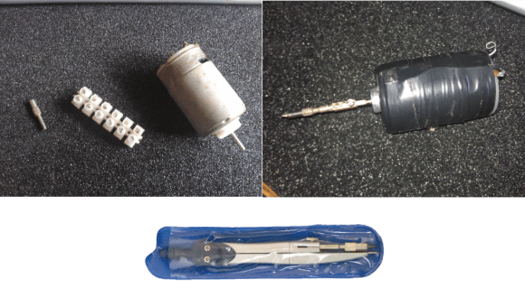
It was a link to DoubleRobotics that got the creative juices flowing. [Chris] and his team wanted to bring [Timo] into the room, but they didn’t have a spare $2499 USD in their budget. Instead they mated a standard motorized pan/tilt camera base with an RFduino Bluetooth kit. An application running on [Timo’s] phone sends gyroscope status through the internet to the iPad on the robot. The robot’s iPad then sends that data via Bluetooth to the RFduino. The RFduino commands pan and tilt movements corresponding with those sensed by the gyroscope. A video chat application runs on top of all this, allowing [Timo] to look around the room and converse with his coworkers.
All the source code is available via GitHub. The design didn’t work perfectly at first. [Chris] mentions the RFduino’s Bluetooth API is rather flaky when it comes to pairing operations. In the end the team was able to complete the robot and present it to [Timo] as a Valentine’s Day gift. For [Chris’] sake we hope [Timo] doesn’t spend too much of his time doing what his homepage URL would suggest: “screamingatmyscreen.com”
[Thanks Parker]