String Racing Robots Are Here !

This could be the start of a new thing. [HarpDude] showed off his String Car Racers over on the Adafruit forum. It’s like a small model cable car on caffeine. String up enough of them and go head to head racing with others.

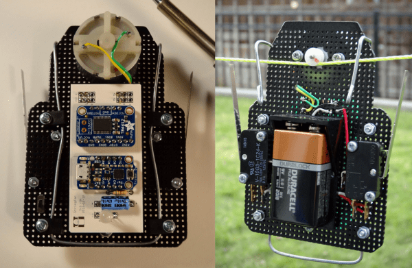
A motor with a small pulley runs over a length of string stretched between 2 posts. Below the pulley, acting as a counterweight balance, is the rest of the racer. A Trinket board, motor driver, 9V battery and a pair of long lever micro switches to detect end of travel. The switches also help reverse the motor. A piece of galvanized wire acts as a guide preventing the String Car from jumping off the string. And discovering the benefits of a micro-controller design, as against discrete TTL/CMOS, old timer [HarpDude] added two operational modes via software. “Pong”, where the String Car keeps going back and forth over the string until it stops of (battery) exhaustion. The other mode is “Boomerang” – a single return trip back and forth.

We are guessing the next upgrade would be to add some kind of radio on the car (ESP8266 perhaps) and build an app to control the String Car. That’s when gaming could become fun as it opens up possibilities. One way to improve performance would be to add two “idler” pulleys in line with the main drive pulley, and then snake the string through the three of them. Now you know what to do with all of those old motors you’ve scavenged from tape drives, CD drives and printers. Let the Games begin!

Thanks [Mike Stone] for tipping us off on this.

Rube Slowberg

This one was buried in our tips line for a couple of months, but we’re glad it eventually surfaced. [Bob Partington] built the “Rube Slowberg” contraption – it’s billed as the world’s slowest Rube Goldberg Machine. The golf ball that he tee’d off took six weeks to reach it’s rather dramatic end.

Rube Goldberg machines are fascinating, but most often the fun ends quite quickly. [Bob] decided to slow it all down and it took several hacks to get that done. Thankfully for us, the edited video with extensive use of stop-motion and fast forwards brings the chase down to under three minutes.

Check out the video below. It starts with the Golf ball riding a slow boat on molasses, hitching a ride on a Tortoise, running through a series of melting popsicle sticks and then being propelled one tiny bit at a time by a bunch of growing grass. If you are interested is seeing behind the scenes, watch the other video where he talks a little about how he managed to pull it off.

Continue reading “Rube Slowberg”

Simple Solar Mason-Jar Lights

[Michael Mogenson] built Firefly Jar – a simple circuit to light up firefly_jar_01
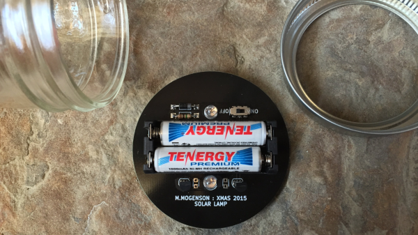
flickering LEDs inside a standard Mason Jar, to give away to friends and family for the holidays. Given it’s simplicity and through-hole design, it’s an ideal project for a “learn to solder” class or for those wanting to get started with building some really simple electronics. There’s just a handful of parts and putting it together shouldn’t take long. Given that he’s made available all of the source design files, it should be easy for others to spin off the project.

A 55mm solar cell fits on top of the 63.5mm diameter PCB, which in turn fits perfectly in a standard Mason Jar with a collar lid. When in the light, the solar cell charges two 1.2V NiMH batteries. This also switches off the P-channel MOSFET, turning the LED’s off. The LED’s are turned on only when the solar cell voltage is low and the Ni-Mh batteries are charged. A 2.1V LDO directly drives the two LEDs with built-in flickering circuits, eliminating the need for any further parts. Check out the video of the Firefly Jar below.

Continue reading “Simple Solar Mason-Jar Lights”

Current Meter Shows Current Time

This isn’t the first of its type, but [Daniel]’s MSP430 based Analog Gauge Clock certainly ticks off the “hack” quotient. He admits an earlier Voltmeter Clock we featured a while back inspired him to build his version.

[Daniel] was taking an Embedded systems class, and needed to build an MSP430G2553 microcontroller based final project. Which is why he decided to implement the real time clock using the micro-controller itself, instead of using an external RTC module. This also simplified the hardware used – the microcontroller, a crystal, three analog ammeters, and a few passives were all that he needed. Other than the Ammeters, everything else came from his parts bin. Fresh face plates were put on the ammeters, and the circuit was assembled on a piece of strip board. A piece of bent steel plate served as the housing.

The interesting part is the software. He wrote all of it in bare C, without resorting to using the Energia IDE. He walks through all of the important parts of his code on his blog post. Setting load capacitance for the timing crystal was important, so he experimented with an oscilloscope to see which value worked best. And TI’s Application Note on MSP430 32-kHz Crystal Oscillators (PDF) proved to be a useful resource. Three PWM output’s run the three ammeters which indicate hours, minutes and seconds. Push-button switches let him set the clock. See a short demo of the clock in the video below.

Continue reading “Current Meter Shows Current Time”

StarMAT Greets Visitors With The Imperial March

Strong is the Force, with this Padawan. To coincide with the latest installment of the continuing saga from a galaxy far, far away, [Rohit Gupta] built a Star-Wars themed interactive doormat. The doormat detects a footstep using capacitive sensing and plays a random Star Wars audio clip like the opening theme or the Imperial March or a famous phrase from the movie. Check out the video below the break.

The current setup is temporarily breadboarded, but we are sure it will be popular enough with his visitors to make him tidy it up. The hardware consists of an Arduino with an audio shield connected to a pair of speakers. A capacitive wire loop under the mat and a capacitive sensor tuned to the mat size wire take care of the sensing.

When Earth people step on the mat, the sensor triggers the Arduino to play a random audio clip from the SD card. The capacitive sensing is taken care by the TP223 1-key touch pad detector chip (PDF), which he mounted on a home etched board with SMD parts. The whole bundle is powered by a small “power bank” battery pack like the ones used to charge mobile phones.

Continue reading “StarMAT Greets Visitors With The Imperial March”

Break Your Wrist? Twitter-Enable That Plaster Cast

Plaster casts are blank canvases for friends and family to post their get well messages. But if it’s holiday season, adding blinky LED lights to them is called for. When [Dr Lucy Rogers] hurt her hand, she put a twitter enabled LED Christmas tree on her cast.

The hardware is plain simple – some RGB LEDs, an Arduino, a blue tooth module and a battery. The LEDs and wires formed the tree, and all the parts were attached to the plaster cast using Velcro. This allowed the electronics to be removed during future X-ray scans. The fun part was in connecting the LEDs to the #CheerLights project. CheerLights is an “Internet of Things” project that allows people’s lights all across the world to synchronize to one color set by a Tweet. To program the Arduino, she used code written by [James Macfarlane] which allowed the LED color to be set to any Cheerlights color seen in blue tooth UART data.

Connectivity is coordinated using MQTT — lightweight standard popular with connected devices. By connecting the MQTT feed to the cheerlights topic from [Andy Stanford-Clark’s] MQTT feed (mqtt://iot.eclipse.org with the topic cheerlights) the lights respond to tweets (Tweet #cheerlights and a color). The LED colors can also be selected via the phone from the color picker tool in the controller, or directly via the UART. If the Bluetooth connection is lost, the LEDs change colors randomly. Obviously, delegates had great fun when she brought her Twitter enabled LED blinky lights plaster cast arm to a conference. It’s not as fun unless you share your accomplishments with others!

Eagle To KiCad Made Easy

One barrier for those wanting to switch over from Eagle to KiCad has been the lack of a way to convert existing projects from one to the other. An Eagle to KiCad ULP exists, but it only converts the schematic, albeit with errors and hence not too helpful. And for quite some time, KiCad has been able to open Eagle .brd layout files. But without a netlist to read and check for errors, that’s not too useful either.

[Lachlan] has written a comprehensive set of Eagle to KiCad ULP scripts to convert schematics, symbols and footprints. Board conversion is still done using KiCad’s built in converter, since it works quite well, and we were able to successfully convert two projects from Eagle. The entire process took only about 10 to 15 minutes of clean up after running the scripts.

The five scripts and one include file run sequentially once the first one is run. [Lachlan]’s scripts will convert Eagle multi sheet .sch to KiCad multi sheets, place global and local net labels for multi sheets, convert multi part symbols, build KiCad footprint modules and symbol libraries from Eagle libraries, create a project directory to store all the converted files, and perform basic error checking. The Eagle 6.xx PCB files can be directly imported to KiCad. The scripts also convert Via’s to Pads, which helps with KiCad’s flood fill, when Via’s have no connections — this part requires some manual intervention and post processing.