Repairing A Twisted Prius Display Computer

This one is from way back in 2007, but the steps [hobbit] took to evaluate and repair a failed Prius Multi-Function Display (MFD) is a refresher course in how to go about fixing stuff that’s broken.

The 2004 / 2005 models of the Prius had peculiar problems with their MFD. Buttons and touch functions became sluggish and unresponsive, it wouldn’t display ECU data such as current and average fuel consumption, and couldn’t control stereo and air-conditioning. Lots of Prius users were reporting similar problems on the Priuschat forum.

The issues would usually arise long after warranty expired, and replacement units cost a couple of thousand dollars new. Toyota knew what the problem was (PDF link), but their fix involved swapping the defective units out.

[hobbit] managed to get a defective MFD unit from a friend, and because his own Prius still had a working MFD, he was able to carry out comparative tests on both units. The broken unit was generally laggy, and the buttons didn’t beep when pressed. Apparently, the AVCLan, a small data network between various components in the car, wasn’t reaching the MFD reliably. The MFD would send the “beep” command to the audio amplifier and wait for a confirmation that would never arrive. The system hung here until the MFD timed out.

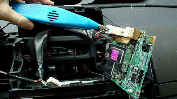
In the end, the cause of the problem was the 60-pin micro connector that interfaces the two main boards of the MFD. Once the two are mated, tightening the mounting screws twisted the two boards ever so slightly, leading to flaky contacts.

The fix? [hobbit] tweaked all of the 60 pins outwards enough that they still made contact even when the connector housing got twisted. Comparing the defective MFD to the one in [hobbit]’s own car also demonstrated how the factory fixed the problem.

Thanks to [Nick] for sending in this tip, which he stumbled upon “while searching for ideas for a very small solder tip to repair something on my laptop.”

KiCad Script Hack For Better Mechanical CAD Export

Open source EDA software KiCad has been gaining a lot of traction recently. CERN has been devoting resources to introduce many new advanced features such as differential pair tracks, push and shove routing and this plenty more scheduled in the pipeline. One important requirement of EDA packages is a seamless interface with mechanical CAD packages by exporting 3D models in industry common formats. This improves collaboration and allows further engineering designs such as enclosures and panels to be produced.

KiCad has had a 3D viewer available for quite a long time. But it uses the VRML mesh format (.wrl files) and there are compatibility issues which prevent it from rendering certain versions of VRML files. Moreover, the VRML mesh export is not particularly useful since it cannot be easily manipulated in mechanical CAD software. Recent versions of KiCad now offer IDFv3 format export – the Intermediate Data Format, a mechanical data exchange specification for the design and analysis of printed wiring assemblies. Taking advantage of this new feature, [Maurice] created KiCad StepUp – an export script that allows collaborative exchange between KiCad and FreeCAD.

A FreeCAD macro and a corresponding configuration file are added to the KiCad project folder. You start with .STEP files for all the components used in the KiCad design. The next step is to convert and save all .STEP files as .WRL format using FreeCAD. On the KiCad side, you use the .WRL files as usual. When you want to export the board, use the IDFv3 option in KiCad. When [Maurice]’s StepUp script is run (outside of KiCad) it replaces all instances of .WRL files with the equivalent .STEP versions and imports the board as well as the components in to FreeCAD as .STEP models. The result is a board and its populated components which can be manipulated as regular 3D objects.

Continue reading “KiCad Script Hack For Better Mechanical CAD Export”

Electronic Float Valve Keeps The Horse’s Feet Dry

[Bob] built this simple device that can best be described as an electronic float valve. He was wasting a lot of water from overflowing water troughs and buckets around his farm. He would usually put the hose in the container, turn on the water valve and carry on with his work. By the time he remembered to come back, the area would be flooded. It’s obvious that there’s many different ways to solve a problem. For example, a simple mechanical float valve might have worked, but it’s not horse friendly and liable to get damaged soon.

The electronics is unabashedly minimal. An ATtiny85 controls a relay via a common variety NPN transistor. The relay in turn switches the solenoid valve. A push-button tells the microcontroller to start the water flowing, and when the water level gets high enough that it touches two hose clamps, the micro shuts it off again.

There’s some ghetto engineering going on here. The electronics is driven by a 9V battery, although the relay and the solenoid valve that [Bob] used are both rated for 12V. He’s not even using any sort of voltage regulation for the ATtiny, but instead dropping the voltage with a resistor divider. (We wonder about battery life in the long run.)

He built all of it on perf board and stuffed it inside a small enclosure, with two wires coming out for the level sensor and another two for the solenoid, and it seems to work. Check the video below where [Bob] walks through his build.

While some may point out the many short comings in this build, [Bob] found the one solution that works for him. Sometimes the right solution is what you’ve got on hand, and we’re glad he’s hacking away and sharing his work. And check out this wireless water level sensor that he built some time back.

Continue reading “Electronic Float Valve Keeps The Horse’s Feet Dry”

Escape Cable Hell With An Audio I/O Multiplexer

If you ever find yourself swapping between a mix of audio inputs and outputs and get tired of plugging cables all the time, check out [winslomb]’s audio multiplexer with integrated amplifier. The device can take any one of four audio inputs, pass the signal through an amplifier, and send it to any one of four outputs.

The audio amplifier has a volume control, and the inputs and outputs can be selected via button presses. An Arduino Pro Mini takes care of switching the relays based on the button presses. On the input side, you can plug in devices like a phone, TV, digital audio player or a computer. The output can be fed to speakers, headsets or earphones.

At the center of the build lies a TI TPA152 75-mW stereo audio power amplifier. This audio op-amp is designed to drive 32 ohm loads, so performance might suffer when connecting it to lower impedance devices, but it seems to work fine for headphones and small computer speakers. The dual-gang potentiometer controls the volume, and the chip has a useful de-pop feature. The circuit is pretty much a copy of the reference shown in the data sheet. Switching between inputs or outputs is handled by a bank of TLP172A solid state relays with MOSFET outputs, and it’s all tied together with a micro-controller, allowing for WiFi or BLE functionality to be added on later.

[winslomb] laid out the design using Eagle and he made a couple of footprint mistakes for the large capacitors and the opto-relays. (As he says, always double-check part footprints!) In the end, he solder-bridged them on to the board, but they should probably be fixed for the next revision.

[winslomb] built the switch as his capstone project while on his way to getting a Masters in EE, and although the device did function as required, there is still room for improvement. The GitHub repository contains all the hardware and software sources. Check out the video below where he walks through a demo of the device in action. If you are looking for something simpler, here is a two input – one output audio switcher with USB control and on the other end of the spectrum, here’s an audio switch that connects to the Internet.

Continue reading “Escape Cable Hell With An Audio I/O Multiplexer”

Dalek-Berry-Pi Mower

There’s something about lawn mowers and hackers. A desire to make them into smart, independent robots. Probably in preparation for the day when Skynet becomes self-aware or the Borg collective comes along to assimilate them into the hive. [Ostafichuk] wanted his to be ready when that happens, so he’s building a Raspberry-Pi powered, Dalek costumed Lawn Mower that is still a work in progress since starting on it in 2014. According to him,  “commercial robot lawn mowers are too expensive and not nearly terrifying enough to be any fun, so I guess I will just have to build something myself…”

His first report describes the basic skeletal structure he built using scrap pieces of wood. Two large lawn tractor wheels and a third pivot wheel help with locomotion. The two large wheels are driven by geared motors originally meant for car seat height adjustments. A deep cycle 12V battery, and solar panels for charging would take care of power. A raspberry-pi provides the brain power for the Dalek-Mower and L298N based drivers help drive the motors. The body was built from some more planks of scrap wood that he had lying around. While waiting around for several parts to arrive – ultrasonic sensors, accelerometer, 5V power supply modules – he started to paint and decorate the wood work. Generous amounts of water repellent paint and duct tape were used to make it weather proof. His initial plan was to use python for the code, but he later switched to programming in c along with wiringPi library. Code for the project is available from his bitbucket git repository. Load testing revealed that the L298N drivers were not suitable for the high current drawn by the motors, so he changed over to relays to drive them.

Continue reading “Dalek-Berry-Pi Mower”

Developed On Hackaday – HaDge Is Back To The Drawing Board

A couple of days back, we wrote about the HACK – a prototyping platform designed by [Michele Perla] based on the Atmel SAM R21 MCU. It’s one of the new breed of devices consisting of an ARM Cortex-M0 MCU + IEEE 802.15.4 Wireless radio bundled together. This was exciting since we could pack a lot of punch in the HaDge hardware. We planned to use the same design later to power the HaDge. Building HACK would have allowed us to get it in the hands of the software team, while the hardware folks worked on the real HaDge layout.

The HACK design was ready for review and we asked around to verify the antenna layout, which was the part we were not too sure about.  We asked Atmel for help with verifying the layout. That’s when we had the facepalm moment. They asked us – “What about FCC certification?” Since we plan to build the badges in quantities of a few hundred at the very least, it’s obvious we cannot escape from FCC certification. A design based around the R21 is ruled out – the cost of obtaining approval is pretty high. This means we need to punt the R21 and instead use an off-the-shelf radio module which is already FCC certified. Sigh.

Now the good news. This is a setback in terms of time, and effort put in by [Michele]. But beyond that, we’re good to go back to the drawing board and start afresh. First off, we decided to revert back to the Atmel D21 as the main controller. It’s a fairly decent MCU, and there’s a fairly robust tool chain available that a lot of people are familiar with. For the Radio, we are looking at some of these available options :

The last one from Microchip looks quite promising. But we’re open for better and cheaper suggestions, so please chime in with your comments.

Superbike Gets Bootstrapped Instrument Refit

[Josh] got rid of the standard, factory gauges on his GSXR Super-bike and installed a custom built instrument panel which displays some additional parameters which the regular instrumentation cluster did not. He was working on converting his bike in to a Streetfighter – a stripped down, aggressive, mean machine. The staid looking gauges had to go, besides several other mods to give his bike the right look.

GSXR_03
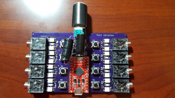
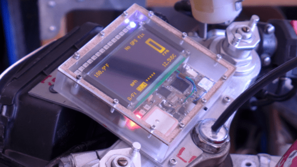
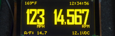
Luckily, he had the right skills and tools available to make sure this DIY hack lives up to the Streetfighter cred of his bike. The important parameter for him was to log the Air / Fuel mixture ratio so he could work on the carburation. Along the way, he seems to have gone a bit overboard with this build, but the end result is quite nice. The build centers around a Planar 160×80 EL graphic display lying in his parts bin. The display didn’t have a controller, so he used the Epson S1D13700 graphic controller to interface it with the microcontroller. An Atmel ATmega128L runs the system, and [Josh] wrote all of his code in “C”.

Continue reading “Superbike Gets Bootstrapped Instrument Refit”