Under The Hood – What Does This Board Do?

As interesting as it is to look at the insides of de-capped chips, it is equally interesting to sometimes look at old circuit boards and try to figure out the various sections, their functions, and to look at some of the design practices used. At a local electronics flea market, [daqq] recently chanced upon quite a large PCB that seemed to have come from some HP system, and picked it up for about 6 – the value of the abundant oscillators, crystals, connectors and other miscellaneous components that could be recovered seemed much more than what he paid for the board.

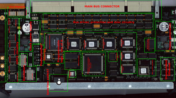
The board in question turned out to be from a HP 9000 Superdome system – part of the PA-8xxx based server series which packs quite a punch. This particular one was the 500MHz system UGUY5-500 board. At this point, most of [daqq]’s analysis is based on what he can visually decipher looking at the chip numbers and associated parts. He’s taken a stab at guessing the function of the board itself, and of the various parts on it. He’s put up high resolution scanned images of the board, for any of our readers who would like to offer an insight in to this board or the system that it was part of. Apparently, he has quite a few more exotic server PCB’s lined up for sleuthing, if you folks enjoy this.

Putting New Into The Old – A Phonograph Upgrade.

[smellsofbikes] recently came into possession of a 1970’s “stereo radio phonograph” cabinet consisting of a vinyl record player, AM and FM radio, and eight track tape player. The radio worked, the turntable didn’t sound too nice, and the tape player didn’t work at all. A new needle fixed the turntable, but the eight-track was in bad shape. So he replaced the tape player with a BeagleBoneBlack which plays streaming internet radio.

Hopefully, this fix is temporary, since he has carefully disconnected the tape player connections in the hope of fixing it soon. The swap out involved a fair bit of engineering, so he’s split his build log into several bite sized chunks. The first step was to set up the BBB, upgrade it and add in all the network and audio related stuff. Audio on the BBB is available only via the HDMI port, but [smellsofbikes] had a USB soundcard handy, so the next step was setting that up. He installed mpg321 – the command line mp3 player and set it up to play music streaming from somafm. Next up was getting some scripts and programs to run automatically during system bootup. The final part of the setup was adding a WiFi router as a repeater connected to the BBB via an ethernet cable. He could have used a tiny WiFi USB dongle, but he already had the router lying around, and he wanted to dedicate USB to audio functions alone, and use the Ethernet port for Internet.

He then worked on identifying the wires that go from the tape player to the amplifier, spliced them, and hooked them up to the audio sound card on the BBB. With this done, the upgrade was more or less complete – the system played streaming music and stations could be switched remotely (via SSH to BBB). [smellsofbikes] reckoned it would be nice to use the existing controls in the phonograph cabinet to control the internet streaming music, instead of controlling it via a remote computer. The cabinet had 4 indicator lamps that indicated which track was being played and a button to switch between tracks. He removed the old indicator panel and put in a fresh PCB, designed in KiCad and cut on his LPKF circuit board plotter. An aluminum knob machined out of hex bar-stock works as the new track change button. At this point, he called it a wrap. The BBB and Asus router go inside the cabinet, and the old (non-functional) tape player is put in place. Quite an interesting build, and we look forward to when he actually gets the tape player working. [Alan Martin], aka “The Most Interesting Engineer In The World” has told him that “it is a moral imperative that you repair the eight-track and get it working”. [Alan] has promised to send [smellsofbikes] a suitcase full of brand new, still in their plastic wrappers, eight-track tapes when he gets it working.

Beating DRM To Extend The Life Of An Anti-Aging Therapy Light Mask

It’s becoming more common to see DRM cropping up in an increasing number of hardware products nowadays. Quite often, its used to prevent the use of unauthorized consumables and some may argue that it helps prevent counterfeiting and help shore up revenues. But it’s a totally different matter when DRM is used to severely limit the operational life of a product. When [travis] wrote in about the run time limitation on an “Illumimask” light therapy device, we first had to look up what that device was. Apparently, these are anti-acne or anti-aging light therapy masks that use red and blue LEDs to kill skin bacteria, stimulate skin cells and reduce blemishes. While these claims most likely may not hold water, the device itself is cheap enough not to hurt you at $30 a pop.

The trouble is, it is limited to 30 daily uses of 15 minutes each, totaling just 7 1/2 hours, effectively lasting you a month. At the end of which, you just discard the device and get a new one. That seems like a ridiculous waste of a perfectly fine, functional device whose LED’s can last at least 30,000 to 40,000 hours. [travis]’s wife [Bebefuzz] was obviously pissed at this situation. So she did a simple hack to bypass the microcontroller that imposed the goofy restrictions. In [travis]’s own words “Not a crazy-technical hack…. but a very functional one to bypass a manufacturer’s ‘WTF'”. It involved soldering a slide switch across the circuit terminals that the micro-controller uses to monitor the LED current (likely). Unfortunately, this also breaks the 15 minute timer measurement, so she now has to manually switch off the device at the end of the 15 minute therapy cycle.

To check out more DRM hacks, check out these we covered earlier, from Coffee Makers to 3D printer filaments to Cat Litter boxes and even furniture.

A Hacker-Friendly Blinky USB Stick

The availability of Smart RGB LED’s, either as individual units, as strips or even as panels, have made blinky light projects with all kinds of color control and transition effects easy to implement using even the simplest of controllers. Libraries that allow control of these smart LEDs (or Smart Pixels as they are sometimes called)  make software development relatively easy.

[overflo] at the Metalab hackerspace in Vienna, Austria recently completed development of usblinky – a hacker friendly blinky USB stick. It can control up to 150 WS2812B smart LED’s when powered via an external power supply, or up to 20 LED’s when powered via a computer USB port. The micro-controller is an ATTiny85 running the Micronucleus bootloader which implements software USB using vUSB. The hardware is based on the DigiSpark platform. The usblinky software sources are available on their Github repo. The section on pitfalls and lessons learned makes for interesting reading.

Metalab plans to run workshops around this little device to get kids into programming, as it is easy enough and gives quick visual feedback to get you started. To round off the whole project, [overflo] used OpenSCAD to design a customizable, 3D printable “parametric orb” which can house the LED strip and make a nice enclosure or psychedelic night light. Check out the mesmerizing video of the usblinky Orb after the break.

Thanks to [papst] for sending in this tip.

Continue reading “A Hacker-Friendly Blinky USB Stick”

How Cheap Is Cheap?

The Nordic Semiconductor nRF24L01 is the older sibling of the nRF24L01+ and is not recommended for new designs anymore. Sometimes, if you’re looking for a cheaper bargain, the older chip may the way to go. [necromant] recently got hold of a bunch of cheap nrf24l01 modules. How cheap ? Does $0.55 sound cheap enough?

Someone back east worked out how to cost-optimize cheap modules and make them even cheaper. At that price, the modules would have severe performance limitations, if they worked at all. [necromant] decided to take a look under the hood. First off, there’s no QFN package on the modules. Instead they contain a COB (chip on board) embedded in black epoxy. [necromant] guesses it’s most likely one of those fake ASICs under the epoxy with more power consumption and less sensitivity. But there’s a step further you can go in making it cheaper. He compared the modules to the reference schematics, and found several key components missing. A critical current set resistor is missing (unless it’s hiding under the epoxy). And many of the components on the transmit side are missing – which means signal power would be nowhere near close to the original modules.

The big question is if they work or not ? In one test, the radio did not work at all. In a different setup, it worked, albeit with very low signal quality. If you are in Moscow, and have access to 2.4Ghz RF analysis tools, [necromant] would like to hear from you, so he can look at the guts of these modules.

Thanks to [Andrew] for sending in this tip.

Fail Of The Week : Measuring DC Current Has To Be Easy, Right?

[DainBramage] needed a DC ammeter to check how long his amateur radio station would be able to stay powered on battery backup power. The one’s he already had on hand were a Clamp Meter, which could only measure AC, and another one that measured just a few milliamps. Since he didn’t have one which could measure up to 25A, he decided to build his own DIY DC Ammeter with parts scavenged from his parts bin. Measuring DC current is not too difficult. Pass the current to be measured through a precision resistor, and measure the voltage drop across it using a sensitive voltmeter.

I = V/R

So far, so good. If it’s late at night and you’ve had a lot of coffee, busy building your DC ammeter, things could head south soon. [DainBramage]’s first step was to build a suitable Shunt. He had a lot of old, 1Ω, 10W resistors lying around. He made a series-parallel combination using nine of them to create a hefty 1Ω, 90W shunt (well, 0.999999999 Ohms if you want to be picky). This gave him a nice 1 Volt per Amp ratio, making it easy to do his measurements.

Next step was to hook up the shunt to a suitable voltmeter. Luckily, he had a Micronta voltmeter lying around, ripped out from a Radio Shack product. Since he didn’t have the voltmeter data, he hooked up a 10k resistor across the meter inputs, and slowly increased the voltage applied to the meter. At 260mV, the needle touched full-scale and the voltage across the inputs of the voltmeter was 33mV. [DainBramage] then describes the math he used to calculate the resistors he would need to have a 10A and a 25A measurement range. He misses his chance to catch the fail. His project log then describes some of the boring details of putting all this together inside a case and wrapping it all up.

A while later, his updates crop up. First thing he probably realized was that he needed more accurate readings, so he added connectors to allow attaching a more accurate voltmeter instead of the analog Micronta. At this point, he still didn’t catch the fail although it’s staring him straight in the face.

His head scratching moment comes when he tries to connect his home made ammeter in series with the 12V DC power supply to his amateur radio station. Every time he tries to transmit (which is when the Radio is drawing some current), the Radio shuts off.  If you still haven’t spotted the fail, try figuring out how much voltage gets dropped across the 1Ω shunt resistor when the current is 1A and when it is 5A or more.

DIY Turntable In A Beautiful Wooden Case

Old timers who have been around for the last 40 years or so have been fortunate enough to have lived through several audio reproduction technologies – Vinyl Records, Cassette Tapes, Laser Disks and CD-ROM’s. Most will also swear that analog, especially vinyl records, sounded the best. And when it comes to amplifiers, nothing comes close to the richness of vacuum tubes.

[MCumic10] had a long time desire to build his own HiFi turntable encased in a nice wooden housing, with the electronics embedded inside. When he chanced upon an old and battered turntable whose mechanism barely worked, he decided to plunge right in to his pet project. The result, at the end of many long months of painstaking work, is a stunning, beautiful, wooden turntable. Especially since in his own words, “I didn’t have any experience in electronics or woodworking before I started this project so it took me many long months in learning analyzing and frustration. I burned some electronic parts few times and made them from the beginning.”

The build is a mix of some off the shelf modules that he bought off eBay and other sources, and some other modules that he built himself. He’s divided the build in to several bite sized chunks to make it easy to follow. The interesting parts are the 6N3 Valve Preamplifier (the main amplifier is solid-state), the motorized Remote Volume Control Input kit, and the Nixie tube channel indicator. And of course the layered, plywood casing. By his own reckoning, this was the toughest and longest part of his build, requiring a fairly large amount of elbow grease to get it finished. He hasn’t yet measured how much it tips the scales, but it sure looks very heavy. The end result is quite nice, especially for someone who didn’t have much experience building such stuff.

Thanks [irish] for sending in this tip.