Friday Hack Chat: Perfect Purple PCBs

Every Friday, we gather ’round the hot air gun over on Hackaday.io, invite some cool people over, and get them to talk about what they do. This is the Hack Chat. It’s become a tradition, and already we’ve had a ton of awesome people walk through our doors.

This Friday, we’re going to sit down with the purveyors of perfect purple PCBs. Over the last decade or so, a lot has changed in the space of small-run PCB production. Ten years ago, PCBs were expensive, and it wouldn’t be abnormal to spend hundreds of dollars on a small run of tiny boards. Now, The DEF CON 24 badge, in a panel are cheaper than ever, giving industrious hardware creators access to professional quality manufacturing at a fraction of the price seen just a few years ago.

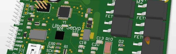
For the last few years, OSH Park has been a mainstay of low-volume PCB fabrication. Their website is as simple as it gets: Upload some Gerbers, an Eagle board file, or a KiCad PCB, press a few buttons, and in a week or so you’ll have a perfect purple PCB in your mailbox.

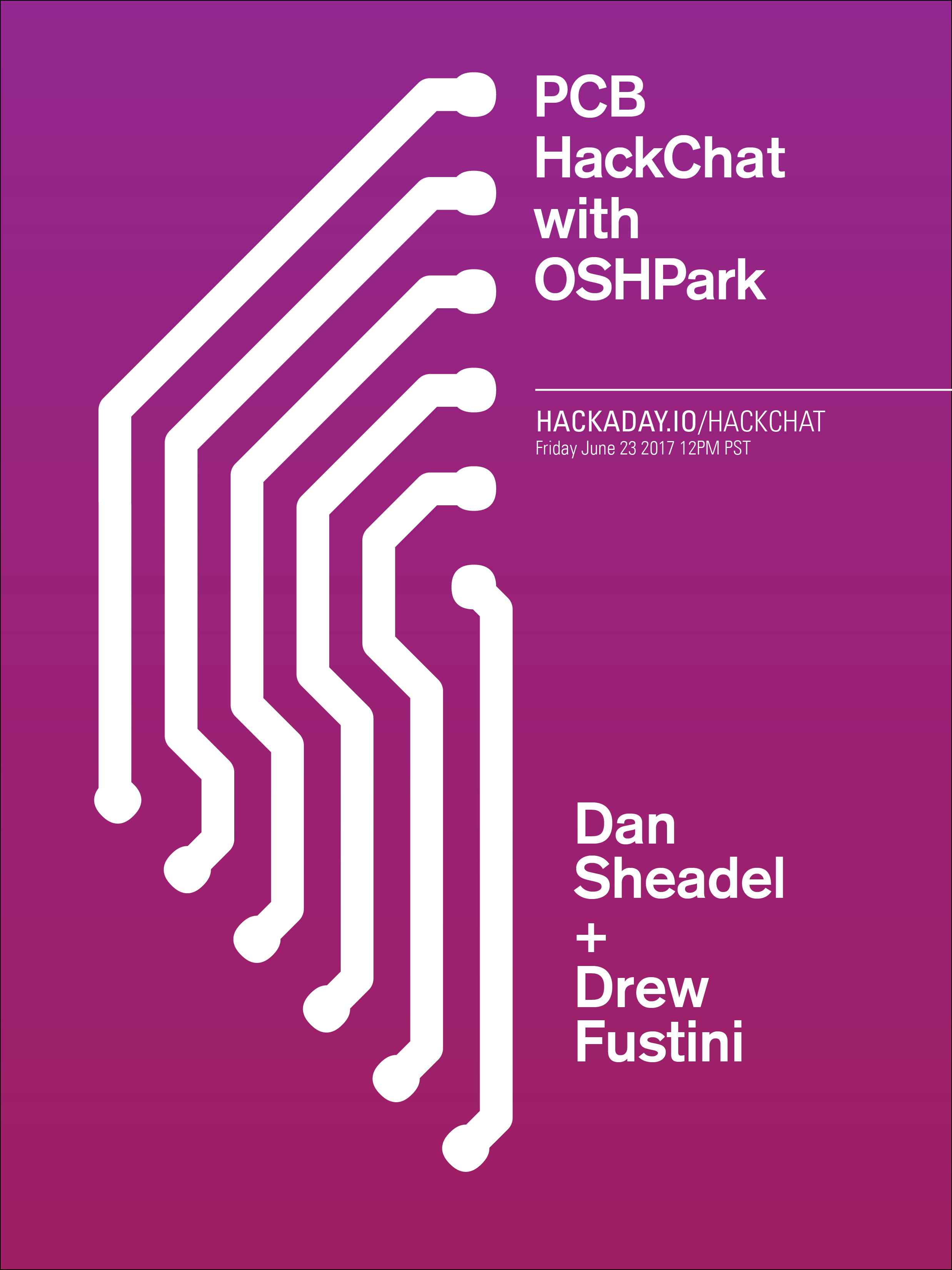
This week, we’re inviting [Drew Fustini] and [Dan Sheadel] to talk about what OSH Park does, how they became the first place that comes to mind when you need a PCB. They’ll explain why the boards are purple, environmental regulations for PCB manufacturing in the US, shared projects and tips and tricks for creating the perfect board.

What would you like to see from a PCB supplier? Would you like to see OSH Park expand further into their burgeoning Pog business? How about a sticker club? Who would win in a fight, a blue robot dog or a purple robot shark? All these questions and more will be answered; if you have a question for the OSH Park team, drop it in this spreadsheet.

Here’s How To Take Part:

join-hack-chatOur Hack Chats are live community events on the Hackaday.io Hack Chat group messaging. This hack chat will take place at noon Pacific time on Friday, June 23rd. Confused about where and when ‘noon’ is? Here’s a time and date converter!

Log into Hackaday.io, visit that page, and look for the ‘Join this Project’ Button. Once you’re part of the project, the button will change to ‘Team Messaging’, which takes you directly to the Hack Chat.

You don’t have to wait until Friday; join whenever you want and you can see what the community is talking about

Reverse Engineering The Monoprice Printer

When the Monoprice MP Select Mini 3D printer was released last year, it was a game changer. This was a printer for $200, yes, but it also held a not-so-obvious secret: a 3D printer controller board no one had ever seen before powered by a 32-bit ARM microcontroller with an ESP8266 handling the UI. This is a game-changing set of electronics in the world of 3D printing, and now, finally, someone is reverse engineering it.

[Robin] began the reverse engineering by attaching the lead of an oscilloscope to the serial line between the main controller and display controller. The baud rate is weird (500 kHz), but apart from that, the commands readily appear in human-parsable text. There is a web server built into the MP Mini printer, and after inspecting the web page that’s served up from this printer, [Robin] found it was possible to send G-code directly from the controller board, get a list of files on the SD card, and do everything you would want to do with a 3D printer.

After deconstructing the circuit on the display board, [Robin] found exactly what you would expect from such a simple board: an SPI display driven by an ESP, and a big flash chip sitting off to the side. [Robin] found the the model of the display, and quickly built a project on Platform.io to draw text to the LCD. This isn’t the end of the project – there’s still a lot that must be done before this printer is squirting out parts with custom firmware.

While this isn’t a hack of the driver board inside the MP Mini, that’s not really a problem. The motor driver board in this printer doesn’t really need any changes, and was already ahead of its time when this printer was released last year. As with most things, the UI is the weak point, and upgrading the firmware and built-in web server for this printer is the best way forward.

[Robin] put together a truly phenomenal video of how he reverse engineered this display controller. You can check that out below.

Continue reading “Reverse Engineering The Monoprice Printer”

The Immersive Flight Simulator From 1989

The history of PC gaming showers games such a Wolfenstein 3D and Doom with the honor of having the most advanced graphics of the day. Often overlooked is Microsoft Flight Simulator and earlier, pre-Microsoft versions from subLOGIC, including the 1977 Apple II version. [Wayne Piekarski] was playing around with MS Flight Simulator 4 recently, and wanted it to be a bit more like his modern flight sim based on X-Plane 11. That meant multiple monitors, and the results are amazing.

The video and networking capabilities for MS Flight Sim 4, while very impressive for the late 80s, are still very limited. In 1989, computers only supported a single display, and while FS4 had the ability to network machines together for dogfighting, there was no way to set the camera viewpoint to the remote aircraft.

The solution to this problem came in the form of memory dumps. Since [Wayne] is running FS4 in DOSBox, he’s able to read the memory of one instance of the game, and write those memory locations to another instance of the game. There were only 18 bytes of memory in the instance of DOSBox that included heading, altitude, roll, and pitch information for the simulated aircraft. [Wayne] is sending this data to other instances of FS4 — effectively mirroring the game on another machine — and changing the camera view to look out the left and right windows. He displayed those views on additional monitors, and was done.

The results are exactly what you would expect. [Wayne] is now taking off from Meigs Field and buzzing the ten or twelve buildings in downtown Chicago with a panoramic 180° view. Check out the videos of that in action below.

Continue reading “The Immersive Flight Simulator From 1989”

Twenty IoT Builds That Just Won $1000 In The Hackaday Prize

Today we’re excited to announce the winners of the Internet of Useful Things phase of The Hackaday Prize. The future will be connected, and this is a challenge to build devices connected to the Internet that are useful. These projects are the best the Internet of Things have to offer, and they just won $1000 each and will move on to the final round of the Hackaday Prize this fall.

Hackaday is currently hosting the greatest hardware competition on Earth. We’re giving away thousands of dollars to hardware creators to build the next great thing. Last week, we wrapped up the second of five challenges. It was all about showing a design to Build Something That Matters. Hundreds entered and began their quest to build a device to change the world.

There are still three more challenges to explore over the next few months. So far, the results have been spectacular. The winners for the Internet of Useful Things portion of the Hackaday Prize are, in no particular order:

Internet of Useful Things Hackaday Prize Finalists:

Continue reading “Twenty IoT Builds That Just Won $1000 In The Hackaday Prize”

Better LEDs Through DMA

While regular Hackaday readers already know how to blink a LED with a microcontroller and have moved onto slightly more challenging projects such as solving the Navier-Stokes equations in 6502 assembly, that doesn’t mean there’s not space for newbies. [Rik] has published a great tutorial on abusing DMA for blinkier glowy things. Why would anyone want to learn about DMA techniques? For blinkier glowy things, of course.

This tutorial assumes knowledge of LED multiplexing and LED matrices, or basically a bunch of LEDs connected together on an XY grid. The naive way to drive an 8×8 grid of LEDs is attaching eight cathodes to GPIO pins on a microcontroller, attaching the eight anodes to another set of GPIO pins, and sourcing and sinking current as required. The pin count can be reduced with shift registers, and LED dimming can be implemented with PWM. This concludes our intensive eight-week Arduino course.

Thanks to microcontrollers that aren’t trapped in the 1980s, new techniques can be used to drive these LED matrices. Most of the more powerful ARM microcontrollers come with DMA, a peripheral for direct memory access. Instead of having the CPU do all the work, the DMA controller can simply shuffle around bits between memory and pins. This means blinker projects and glowier LEDs.

[Rik]’s method for DMAing LEDs includes setting up a big ‘ol array in the code, correctly initializing the DMA peripheral, and wiring up the LED matrix to a few of the pins. This technique can be expanded to animations with 64 levels of brightness, something that would take an incredible amount of processing power (for a microcontroller, at least) if it weren’t for the DMA controller.

The setup used in these experiments is an STM32F103 Nucleo board along with the OpenSTM32 IDE. [Rik] has released all the code over on GitHub, and you are, of course, encouraged to play around.

Hackaday Prize Entry: Very, Very Powerful Servos

A few years ago, [patchartrand] decided to build a robot arm. The specs were simple: he needed a drive system that would be at least as strong as a human arm. After looking at motors, couldn’t find a solution for under $3,000. This led to the creation of the Ultra Servo, an embiggened version of the standard hobby servo that provides more than ten thousand oz-in of torque.

Your typical hobby servo has three main components. The electronics board reads some sort of signal to control a motor. This motor is strapped into a gear train of some sort, and a potentiometer reads the absolute position of a shaft. This is basically what the Ultra Servo is doing, although everything is much, much bigger.

The motor used in the Ultra Servo is a very large brushed DC motor. This is attached to a 160:1 planetary gearbox and the electronics are built around four reasonably large MOSFETs. The electronics are built around the ATmega168 microcontroller, and the specs for the completed servo include 12 V or 24 V operation, TTL, SPI, and standard RC communication, 60 RPM no load speed, and 60 ft-lbs of torque.

This is not your standard servo. This is a massive chunk of metal to move stuff. If you’ve ever wanted a remote-controlled Cessna, here you go. That said, servos of this size and power will always be pricey, and is looking at a cost of $750 per unit. Still, that’s much less than the thousands of a comparable unit, and a great entry to the Hackaday Prize.

Towards DIY Flip Digit Clocks

Seven segment displays and Nixies are one thing, but the king of all antique display technologies must be electromechanical flip dots. These displays, usually found in train stations or rarely on old bus lines, are an array of physical disks, black on one side, light on the other, that ‘flip’ back and forth with the help of an electromagnet. They’re expensive and impressive, driving them is a pain, but oh man do they look awesome.

While flip dot displays can be bought new if you know where to look, [sjm4306] had the idea to build his own out of inexpensive materials. It might just be a prototype, but we’re saying he’s succeeded. He has the workings of a seven flip-segment display, and the techniques he’s using mean it shouldn’t be too expensive to build your own.

Instead of building a matrix of flip dots, [sjm] is building a mechanical seven-segment display. Each of the segments are 3D printed in black PLA, and mounted to a piece of cardboard via a thin wire ‘axel’ going through the length of the segment. Where normal flip dots use an electromagnet to change each dot from one state to another, [sjm] mounted a very small vibrating pager motor to one end of the segment. When one half of a tact switch h-bridge is activated, the segment flips to the front. When the other half of the h-bridge is activated, the segment flips back.

Right now, this hardware is in the ‘extreme prototype’ stage, but results so far are encouraging. [sjm] has already designed a single-segment ‘module’. Plans for the electronics include optocouplers for two microcontroller pins for each segment and reed relays for each individual digit. For a four-digit display, these flip digits will only require 18 I/O pins.

You can check out [sjm4306]’s video for this project below. It’s a little bit long, but watch those things flip!

Continue reading “Towards DIY Flip Digit Clocks”