Upgrading Old Synths To OLED

Roland’s Alpha Juno 2 is an analog, polyphonic synth made in the mid-80s. While it isn’t as capable as the massive synths made around that time, it was very influential synth for the techno scenes of the late 80s and early 90s.

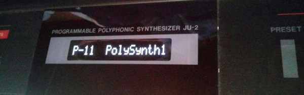
[Jeroen] is lucky enough to have one of these synths, but like all equipment of this era, it’s showing its age. He wanted to replace the character LCD in his Alpha Juno 2 with an OLED display. The original character LCD was compatible with the Hitachi HD44780 protocol, and still today OLEDs can speak this format. What should have been an easy mod turned into editing hex values on the EEPROM, but he still got it to work.

While the original character LCD could display one line of 16 characters, the ROM in the synth didn’t know this. Instead, the display was organized as a 2×8 display in software, with line one starting at address 0h, and line two starting at 40h. For a drop-in replacement, [Jeroen] would need a display the characters organized in this weird 2×8 format. None exist, but he does have a hex editor and an EEPROM burner.

With the Alpha Juno’s firmware in hand thanks to someone who does a few firmware hacks to this synth, [Jeroen] had everything he needed. All that was left to do was going through the code and replace all the references to the second line of the character LCD.

After burning and installing the new ROM, the OLED display was a drop-in replacement. That meant getting rid of the whiney EL backlight in the original display, and making everything nice and glowy for a few nights on a dark stage.

Local Hacker Discovers Card Edge Connectors

When [turingbirds] was looking around for the absolute minimum connector for a JTAG adapter, he wanted something small, that didn’t require expensive adapters, and that could easily and reliably connect a few JTAG pins to a programmer. This, unsurprisingly, is a problem that’s been solved many times over, but that doesn’t mean there isn’t room for improvement. [turingbirds] found his better solution by looking at some old card edge connectors.

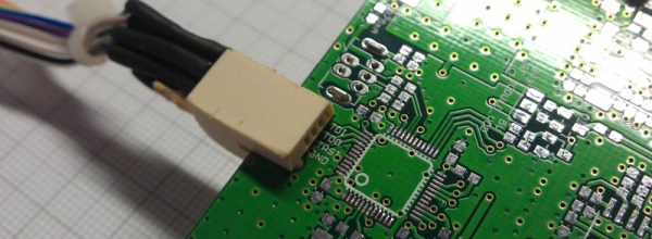
Instead of 0.1″ pitch pin headers, weirder and more expensive connectors, the Tag Connect, or even pogo pins, [turingbirds] came up with a JTAG adapter that required no additional parts, had a small footprint, and could be constructed out of trash usually found behind any busy hackerspace or garage. The connector is based on the venerable PCI connector, chopped up with a Dremel and soldered to a JTAG or ISP programmer.

This is simply a card edge connector, something the younglings seem to have forgotten. Back in the day, card edge connectors were a great way to connect peripherals, ports, and anything else to the outside world. They were keyed, and you could only put them in one way. They were relatively cheap, and with a big coil of ribbon cable, you could make custom adapters easily. For low-speed connections that will only be used a few times, it’s very hard to beat a card edge connector.

Of course the connector itself is only half of the actual build. To turn a chopped up PCI connector into a JTAG adapter, [turingbirds] made footprint and part files for his favorite PCB design tool. In this case it’s Eagle, and the libraries that will plop one of these connectors down are available on GitHub.

Is this the latest and greatest way to plug a programmer into a board? No, because this has been around for 30 or 40 years. It does, however, put a programming port on a PCB with zero dollars in components, a minimum of board footprint, and uses parts that can be salvaged from any pile of old computers.

Adafruit Interviews The CEO Of FTDI

When it comes to electronic hobbyists and EEs, there is no company that deserves a few raised eyebrows than FTDI. They made their name with USB converter chips, namely USB to serial chips that are still very popular today. So popular, in fact, that clones of these chips are frequently found in the $2 Arduinos from China, and other very low-cost devices. A little more than a year ago, a few clever people noticed FTDI drivers were bricking these counterfeit chips by setting the USB PID to 0000. The Internet reacted to this move and FTDI quickly backed down from that position. The Windows driver was fixed, for about a year until the same shenanigans were found again.

Adafruit recently sat down with [Fred Dart], CEO of FTDI, giving us all the first facts and figures that aren’t from people frustrated with Windows’ automatically updated drivers. The most interesting information from [Fred Dart] is how FTDI first found these counterfeit chips, what FTDI chips are being counterfeited, and how many different companies are copying these chips.

The company first realized they were being cloned when they couldn’t reproduce results of a Chinese-made ‘FTDI’ USB to RS232 cable that behaved strangely. A sample of the cables were shipped to FTDI and after inspecting the chip inside, FTDI found it was a clone with a significantly different architecture than a genuine chip.

So far, the counterfeiters appear to only be counterfeiting the SSOP version of the FT232RL and occasionally the older FT232BL chip. From what FTDI has seen, there appears to be only one or two companies counterfeiting chips.

As the CEO of FTDI, [Fred] has a few insights into what can be done to stop counterfeiters in China. The most important is to trademark the logo. This isn’t just the logo for a webpage, but one that can be laser etched onto the plastic package of the chip. US Customs has been very amenable to identifying counterfeit components, and this has led to several shipments being destroyed. Legal action, however, is a bit hard in China, and FTDI is dealing with a gang that counterfeits more than FTDI chips; there’s a high likelihood this gang was responsible for the fake Prolific PL23o3 chips a few years ago.

As far as FTDI bricking counterfeit chips is concerned, [Fred Dart] wasn’t silent on the issue, he merely wasn’t asked the question and didn’t bring it up himself.

The Coming Age Of 3D Integrated Circuits

The pedagogical model of the integrated circuit goes something like this: take a silicone wafer, etch out a few wells, dope some of the silicon with phosphorous, mask some of the chip off, dope some more silicon with boron, and lay down some metal in between everything. That’s an extraordinarily basic model of how the modern semiconductor plant works, but it’s not terribly inaccurate. The conclusion anyone would make after learning this is that chips are inherently three-dimensional devices. But the layers are exceedingly small, and the overall thickness of the active layers of a chip are thinner than a human hair. A bit of study and thought and you’ll realize the structure of an integrated circuit really isn’t in three dimensions.

Recently, rumors and educated guesses coming from silicon insiders have pointed towards true three-dimensional chips as the future of the industry. These chips aren’t a few layers thick like the example above. Instead of just a few dozen layers, 100 or more layers of transistors will be crammed into a single piece of silicon. The reasons for this transition range from shortening the distance signals must travel, reducing resistance (and therefore heat), and optimizing performance and power in a single design.

The ideas that are influencing the current generation of three-dimensional chips aren’t new; these concepts have been around since the beginnings of the semiconductor industry. What is new is how these devices will eventually make it to market, the challenges currently being faced at Intel and other semiconductor companies, and what it will mean for a generation of chips several years down the road.

Continue reading “The Coming Age Of 3D Integrated Circuits”

Hackaday Links: February 7, 2016

For a very long time, the original, 11 foot-long on-screen model of the USS Enterprise from Star Trek the original series – “NCC one seven O one. No bloody A, B, C, or D.” – was housed in the Smithsonian’s Air and Space Museum in Washington, DC. Recent visitors may have noticed the Enterprise is no longer on display. It’s being restored by the finest aircraft conservators in the world. There are a few great videos showing off how much goes into restoring a cultural icon.

Last weekend Hackaday visited Sparklecon in Fullerton, CA. This means I was in LA on the last Saturday of the month. What’s so special about that? The W6TRW Swap Meet at Northrop Grumman in Redondo Beach. Here’s the pics from that. The best thing I found? A wooden acoustic coupler modem for $15. Once I told the guys at the booth what it was, the price went up to $20. Still worth it.

What’s the worst thing about modern computers? They’re all LCDs, and that means worse resolution, terrible colorspace, and monitors that are very, veeeerrrrryyyy wide. The consequence of this is a complete and total lack of screen savers. Never fear, because the flying toaster is back, this time as an SD card holder. It’s 3D printable, so if you have some white, silver, and black filament sitting around, you know what to do.

The USB Killer hit the tips line a few times this week for inexplicable reasons. We’ve seen it before, but we haven’t seen it again. Surprisingly, no one – outside a bizarre Indiegogo campaign that shouldn’t exist – has made their own USB killer. Here’s your call to action: build a USB killer, and I’ll test it out.

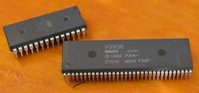
An SDIP-64 chip compared to a DIP-28 chip. Note the finer lead spacing on the SDIP device.

There’s more variety to your standard DIP-packaged chips than you might expect. The weirdest of these – at least when it comes to perfboard construction – is the SDIP, or Skinny Dual In-line Package. Instead of having a standard 0.1″ pitch between leads, the SDIP has a 0.070″ pitch. [Chuck] was having some problems looking for SDIP to DIP adapters until he found this amazing trick the connector companies don’t want you to know aboutJust plop the chip in at a 45º angle, bend a few pins, and you’re good to go.

Graphene Batteries Appear, Results Questionable

If you listen to the zeitgeist, graphene is the next big thing. It’s the end of the oil industry, the solution to global warming, will feed and clothe millions, cure disease, is the foundation of a space elevator that will allow humanity to venture forth into the galaxy. Graphene makes you more attractive, feel younger, and allows you to win friends and influence people. Needless to say, there’s a little bit of hype surrounding graphene.

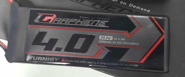
With hype comes marketing, and with marketing comes products making dubious claims. The latest of which is graphene batteries from HobbyKing. According to the literature, these lithium polymer battery packs for RC planes and quadcopters, ‘utilize carbon in the battery structure to form a single layer of graphene… The graphene particles for a highly dense compound allowing electrons to flow with less resistance compared to traditional Lipoly battery technologies” These batteries also come packaged in black shrink tubing and have a black battery connector, making them look much cooler than their non-graphene equivalent. That alone will add at least 5mph to the top speed of any RC airplane.

For the last several years, one of the most interesting potential applications for graphene is energy storage. Graphene ultracapacitors are on the horizon, promising incredible charge densities and fast recharge times. Hopefully, in a decade or two, we might see electric cars powered not by traditional lithium batteries, but graphene supercapacitors. They’ll be able to recharge in minutes and drive further, allowing the world to transition away from a fossil fuel-based economy. World peace commences about two weeks after that happens.

No one expected graphene batteries to show up now, though, and especially not from a company whose biggest market is selling parts to people who build their own quadcopters. How do these batteries hold up? According to the first independent review, it’s a good battery, but the graphene is mostly on the label.

[rampman] on the RCgroups forums did a few tests on the first production runs of the battery, and they’re actually quite good. You can pull a lot of amps out of them, they last through a lot of charging cycles, and the packaging – important for something that will be in a crash – is very good. Are these batteries actually using graphene in their chemistry? That’s the unanswered question, isn’t it?

To be fair, the graphene batteries shipped out to reviewers before HobbyKing’s official launch do perform remarkably well. In the interest of fairness, though, these are most certainly not stock ‘graphene’ battery packs. The reviewers probably aren’t shills, but these battery packs are the best HobbyKing can produce, and not necessarily representative of what we can buy.

It’s also doubtful these batteries use a significant amount of graphene in their construction. According to the available research, graphene increases the power and energy density of batteries. The new graphene batteries store about as much energy as the nano-tech batteries that have been around for years, but weigh significantly more. This might be due to the different construction of the battery pack itself, but the graphene battery should be lighter and smaller, not 20 grams heavier and 5 mm thicker.

In the RC world, HobbyKing is known as being ‘good enough’. It’s not the best stuff you can get, but it is cheap. It’s the Wal-Mart of the RC world, and Wal-Mart isn’t introducing bleeding edge technologies that will purportedly save the planet. Is there real graphene in these batteries? We await an in-depth teardown, preferably with an electron microscope, with baited breath.

Reverse Engineering A WiFi Security Camera

The Internet of Things is slowly turning into the world’s largest crappy robot, with devices seemingly designed to be insecure, all waiting to be rooted and exploited by anyone with the right know-how. The latest Internet-enabled device to fall is a Motorola Focus 73 outdoor security camera. It’s quite a good camera, save for the software. [Alex Farrant] and [Neil Biggs] found the software was exceptionally terrible and would allow anyone to take control of this camera and install new firmware.

The camera in question is the Motorola Focus 73 outdoor security camera. This camera connects to WiFi, features full pan, tilt, zoom controls, and feeds a live image and movement alerts to a server. Basically, it’s everything you need in a WiFi security camera. Setting up this camera is simple – just press the ‘pair’ button and the camera switches to host mode and sets up an open wireless network. The accompanying Hubble mobile app scans the network for the camera and prompts the user to connect to it. Once the app connects to the camera, the user is asked to select a WiFi connection to the Internet from a list. The app then sends the security key over the open network unencrypted. By this point, just about anyone can see the potential for an exploit here, and since this camera is usually installed outdoors – where anyone can reach it – evidence of idiocy abounds.

Once the camera is on the network, there are a few provisions for firmware upgrades. Usually, firmware upgrades are available by downloading from ‘private’ URLs and sent to the camera with a simple script that passes a URL directly into the shell as root. A few facepalms later, and [Alex]  and [Neil] had root access to the camera. The root password was ‘123456’.

While there’s the beginnings of a good Internet of Camera in this product, the design choices for the software are downright stupid. In any event, if you’re looking for a network camera that you own – not a company with a few servers and a custom smartphone app – this would be near the top of the list. It’s a great beginning for some open source camera firmware.

Thanks [Mathieu] for the tip.