DIY Air Quality Sensor


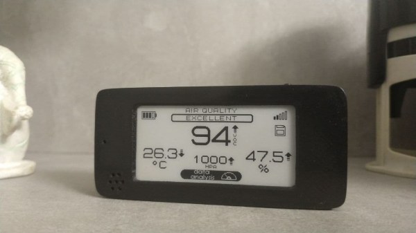
[Andrew Lamchenko], who has built a number of small e-ink-based sensors this year, released another design called the eON Indoor Air Quality Sensor. As his previous sensor designs, the eON boasts a striking appearance with all the spit and polish of a commercially made product. Except [Andrew]’s design is completely open-source.

Besides showing air quality, it also shows basic weather conditions, and there’s a built-in weather forecasting algorithm as well. It can operate standalone or use the radio module to send readings to a smart home system.

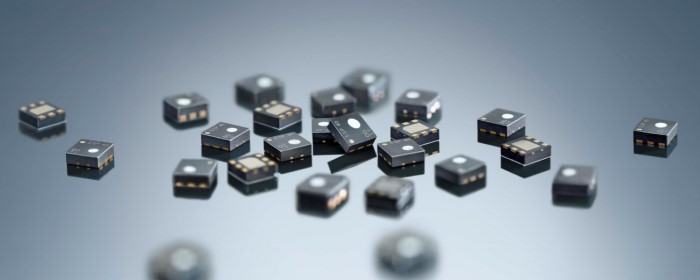
The core sensor is the SGP40, which detects volatile organic compounds (VOCs) in the air while consuming less than 3 mA (compared to the 48 mA of the previous generation). There’s a temperature, barometric pressure, humidity, and light sensors in the package as well. Like many projects these days, [Andrew] encountered parts supply issues along the way. Because of that, and to make the design more flexible, several versions of the board have been made to accommodate the different permutations of:

  • Displays
    • 2.13-inch e-ink display
    • DES e-ink display, coming soon
  • Radio, four flavors
    • MINEW MS88SF3 (nRF52833, nRF52840)
    • MINEW MS50SFA1 (nRF52810, nRF52811)
    • MINEW MS50SFA2 (nRF52832)
    • EBYTE E73-2G4M08S1C (nRF52833, nRF52840)
  • Temp / Pressure sensor:
    • BME280
    • BMP280
    • SHTC3

[Andrew] not only designed the sensor but has done a thorough job on the documentation. Check out the GitHub repository of the project for a complete data package covering all aspects of the design, including the weather forecasting app note by John Young (an NXP engineer, not the astronaut). Last week the design was named as a finalist of the 2021 Hackaday Prize. We’re excited to see where he goes with this between now and the end of October!

Do you use an air quality sensor in your home? If so, is it only for informational purposes or do you take action based on the data, such as automatically turning on a fan or escaping to the countryside? Let us know in the comments below.

Hacking Old Honda ECUs

Automotive security specialist by day [P1kachu] hacks his own cars as a hobby in his free time. He recently began to delve into the Engine Control Units (ECUs) of the two old Hondas that he uses to get around in Japan. Both the 1996 Integra and the 1993 Civic have similar engines but different ECU hardware. Making things more interesting; each one has a tuned EPROM, the Civic’s being of completely unknown origin.

[P1kachu] took his Civic to a shop to have some burned-out transistors replaced in the ECU, and a chance conversation with the proprietor [Tuner-san] sends him on a journey into the world of old EPROMs. [Tuner-san] pulled out an old PROM duplicator stashed away under the counter which he originally used as a kid to copy PROM chips from console games like the Famicom. These days he uses it to maintain a backup collection of old ECU chips from cars he has worked on. This tweaked [P1kachu]’s curiosity, and he wondered if he could obtain the contents of the Civic’s mysterious PROM. After a false start trying to use the serial port on the back of the PROM copier, he brute-forces it. A few minutes of Googling reveals the ASCII pinout of the 27C256 EPROM, and he whips out an Arduino Mega and wires it up to the chip and is off and running.

Advantest R4945A EPROM Duplicator c.1980s

He’s currently digging into the firmware, using IDA and a custom disassembler he wrote for the Mitsubishi M7700 family of MCUs. He started a GitHub repository for this effort, and eventually hopes to identify what has been tweaked on this mysterious ECU chip compared to factory stock. He also wants to perform a little tuning himself. We look forward to more updates as [P1kachu] posts the results of his reverse engineering efforts. We also recommend that you be like [P1kachu] and carry an Arduino, a breadboard, and some hookup wire with you at all times — you never know when they might come in handy. Be sure to checkout our articles about his old Subaru hacks from in 2018 if these kinds of projects interest you.

Quick And Simple Morse Decoder

[Rostislav Persion] wrote a simple Morse Code decoder to run on his Arduino and display the text on an LCD shield. This is probably the simplest decoder possible, and thus its logic is pretty straightforward to follow. Simplicity comes at a price — changing the speed requires changing constants in the code. We would like to see this hooked up to a proper Morse code key, and see how fast [Rostislav] could drive it before it conks out.

In an earlier era of Morse code decoders, one tough part was dealing with the idiosyncrasies of each sender. Every operator’s style, or “fist”, has subtle variations in the timings of the dots, dashes, and the pauses between these elements, the letters, and the words. In fact, trained operators can recognize each other because of this, much like we can often recognize who is speaking on the phone just by hearing their voice. The other difficulty these decoders faced was detecting the signal in low signal-to-noise ratio environments — pulling the signal out of the noise.

A Morse decoder built today is more likely to be used to decode machine-generated signals, for example, debugging information or telemetry. This would more than likely be sent at fixed, known speeds over directly connected links with very high S/N ratios (a wire, perhaps). In these situations, a simple decoder like [Rostislav]’s is completely sufficient.

We wrote about a couple of Morse code algorithms back in 2014, the MorseDetector and the Magic Morse algorithm. While Morse code operators usually rank their skills by speed — the faster the better — this Morse code project for very low power transmitters turns that notion on its head by using speeds more suitably measured in minutes per word (77 MPW for that project). Have you used Morse code in any of your projects before? Let us know in the comments below.

Astronomic Patio Light Timer

Not satisfied with the handheld remote control for his outdoor patio lights, [timabram] decided to build an automatic timer using an ESP8266. He’s using a set of string lights from Costco, but as you dig into his project you’ll see the method he uses can be applied to almost any set of lights that have a remote.

He does this by connecting GPIO pins from the ESP8266 GPIO into the remote control in order to simulate a user pressing the button. Both boards are packaged together in a 3D-printed enclosure that utilizes the front portion of the remote control, so that manual operation is still possible.

His firmware gets the date and time from an NTP server, and then makes an API call to an online service that returns the local sunrise and sunset times for a specific location. He tries to minimize the power consumption by experimenting with different intervals to wakeup from deep sleep and ping the time server. But in the end, he realizes the RF remote control carries quite some distance, and installed the unit inside a closet where it could be powered by adaptors connected to the mains.

We wondered how the remote control knows if the lights are on or off, and [timabram] notes this is a shortcoming which could be addressed in a future version. If you’ve ever seen a mechanical version of an astronomic timer switch, packed full of gears and dials and setting pins, you can really appreciate a no-moving-parts solutions like this project. If you want to make one that doesn’t use the internet, check out this Arduino-based solution that we wrote about back in 2013.

PiNet — One Small Project Grows Unexpectedly

A few years ago, [Gregory Sanders] aka [Dr Gerg] had one simple wish in mind when he started what is now the PiNet project — to know whether his garage door was open or closed. Instead of searching out off-the-shelf solutions, he looked at the project as a learning opportunity. After picking up Python, he built a system from a Raspberry Pi, a 12V gel cell battery, and a power supply / charger circuit. Thus project Overhead Door (ohd) was complete (see the ohd GitHub repository) and [Dr Gerg] was done.

Or so he thought. After getting a swimming pool installed, he got the itch again, and started a new project called Pool Controls, because:

The controls for your average backyard in-ground pool are pathetic. I felt like I could do better with a Raspberry Pi, a relay board and some Python. And so I did, and frankly, it’s awesome.

Then he built his own weather station to replaced a commercial one which had died twice in as many years, followed by his own web-based UI framework. Next was the integration of an outdoor security camera system. And finally, although we don’t believe it’s really final, he ripped out the cloud-based controls from his shop air conditioner and added his own Raspberry Pi-based solution. All of these projects are available on his GitHub page.

[Dr Gerg]’s goal in posting all this work is not necessarily so people can duplicate it, although that is okay as well. Instead, he hopes that people will realize that they can build these types of projects on their own, perhaps leaning some things and picking up new skills along the way — have fun doing it. We like the way you think, [Dr Gerg]. Do you know of any small projects which grew and grew and took on a life of their own?

Print Your Own Flexures

Game developer and eternal learner [David Tucker] just posted a project where he’s making linear flexures on a 3D printer. Tinkerer [Tucker] wanted something that would be rigid in five of the six degrees of freedom, but would provide linear motion along one axis. In this case, it is for a pen or knife on a CNC flatbed device. [David]’s design combines the properties of a 1-dimensional flexure and a spring to give a constant downward force. Not only is this an interesting build in and of itself, but he gives a good explanation and examples of more traditional flexible constructs. He also points out this site by MIT Precision Compliant Systems Lab engineer [Marcel Thomas] which provides a wealth of information on flexures.

Continue reading “Print Your Own Flexures”

Pi Pico-Powered ATX Motherboard

For a couple of years, embedded developer and Rust addict [Jonathan Pallant] aka [theJPster] has been working on a simple computer which he calls the Neotron. The idea is to make a computer that is not only easy to use but easy to understand as well. He describes it as a CP/M- or DOS-like operating system for small ARM microcontrollers. His most recent project is powered by a Raspberry Pi RP2040 Pico and built in the format of a microATX motherboard. This board packs a lot of features for a Pico-based design, including 12-bit color VGA and seven expansion slots. See his GitHub repository for a full list of specifications, and all the files needed to build your own — it is an Open Source project after all.

Besides the Neotron Pico itself, a couple of gems caught our eye in this well-documented project. [theJPster] was running out of I/O pins on the Pico, and didn’t have enough left over for all the peripherals’ chip selects. Check out how he uses an MCP23S17 SPI-bus I/O expander and a tri-state buffer to solve the problem.

On a more meta level, we are intrigued by his use of GitHub Actions. Per the standard concept of repositories, they shouldn’t contain the results of a build, be that an executable binary or Gerber files. Distribution of the build products is typically handled outside of GitHub, using something like GitHub’s Large File Storage service, or just ignoring convention altogether and putting them in the repo anyway. [theJPster] uses another method, employing GitHub Actions to generate the files needed for PCB fabrication, for example.

The Neotron Pico is the latest in a series of boards made to run Neotron OS. Previous boards include:

  • Neotron 9x — Microchip SAM9X
  • Neotron 1000 — STM32H7 + Lattice Semi iCE40 FPGA
  • Neotron 600 — Teensy 4.1
  • Neotron 340ST — ST 32F746G-DISCOVERY