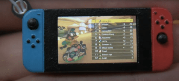
It constantly amazes us what we hackers can build these days, (electronics shortages aside) we have access to an incredible array of parts, with specifications that only a few years ago would be bank-breaking and longer ago just fantasy. It’s nice to see people building one-offs just for fun, in spite of the current difficulties getting parts to actually be delivered. For example, check out this miniaturized Nintendo Switch created by [scottbez1] that plays animated GIFs from an SD card on tiny 1.14″ LCD display.
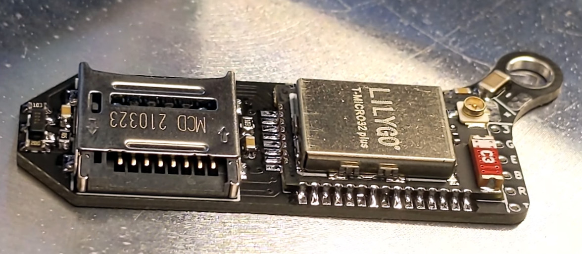
Obviously such a diminutive hack requires a custom PCB, which was a job for KiCAD. Armed with a 3D model of the LCD, the casing and PCB outline were drawn using Fusion 360. The PCB hosts a LilyGo ESP32 module for all the heavy lifting, with the WiFi adding some fun future capabilities not yet explored. The design is about as tight as it can get without pushing the limits of the PCB process too far, including a neat trick of sneaking passives inside the body of the SD card! That’s another space-saving idea we’ll be banking.
All-in-all a neat little hack, showing some good modelling and construction techniques and a good looking end result. Code for your reference may be found on the project GitHub, but as of writing the hardware design is not available.
Whilst this project shrinks the Switch, here’s one that goes the other way and super-sizes it, and if you have a switch lite but crave a little modern charging magic, then look no further than this Qi wireless charging hack.
Continue reading “Tiny Switch Ornament Plays GIFs With An ESP32”