[Arnov] has created a really clean wearable design with great build instructions, so anyone who wants to make their own should have an easy time. Prefer to put your own spin on it, or feel inspired by the wrist-mounted enclosure? He’s thoughtfully provided the CAD files as well.
Inside the PIP-WATCH is a neat piece of hardware, the Lilygo T-Display-S3 Long. It’s an ESP32-based board with a wide, touch-enabled, color 180 x 640 display attached. That makes it a perfect fit for a project like this, at least in theory. In practice, [Arnov] found the documentation extremely lacking which made the hardware difficult to use, but he provides code and instructions so there’s no need to go through the same hassles he did.
What does one do with old circuit boards and projects? Throwing them out doesn’t feel right, but storage space is at a premium for most of us. [Gregory Charvat] suggests doing what he did: combining them all into a wall-mountable panel in order to memorialize them, creating a functional digital clock in the process. As a side benefit, it frees up storage space!
Everything contributes. If it had lights, they light up. If it had a motor, it moves.
Memorializing and honoring his old hardware is a journey that involved more than just gluing components to a panel and hanging it on the wall. [Gregory] went through his old projects one by one, doing repairs where necessary and modifying as required to ensure that each unit could power up, and did something once it did. Composition-wise, earlier projects (some from childhood) are mounted near the bottom. The higher up on the panel, the more recent the project.
As mentioned, the whole panel is more than just a collage of vintage hardware — it functions as a digital clock, complete with seven-segment LED displays and a sheet metal panel festooned with salvaged controls. Behind it all, an Arduino MEGA takes care of running the show.
Creating it was clearly a nostalgic journey for [Gregory], resulting in a piece that celebrates and showcases his hardware work into something functional that seems to have a life of its own. You can get a closer look in the video embedded below the page break.
This really seems like a rewarding way to memorialize one’s old projects, and maybe even help let go of unfinished ones.
And of course, we’re also a fan of the way it frees up space. After all, many of us do not thrive in clutter and our own [Gerrit Coetzee] has some guidance and advice on controlling it.
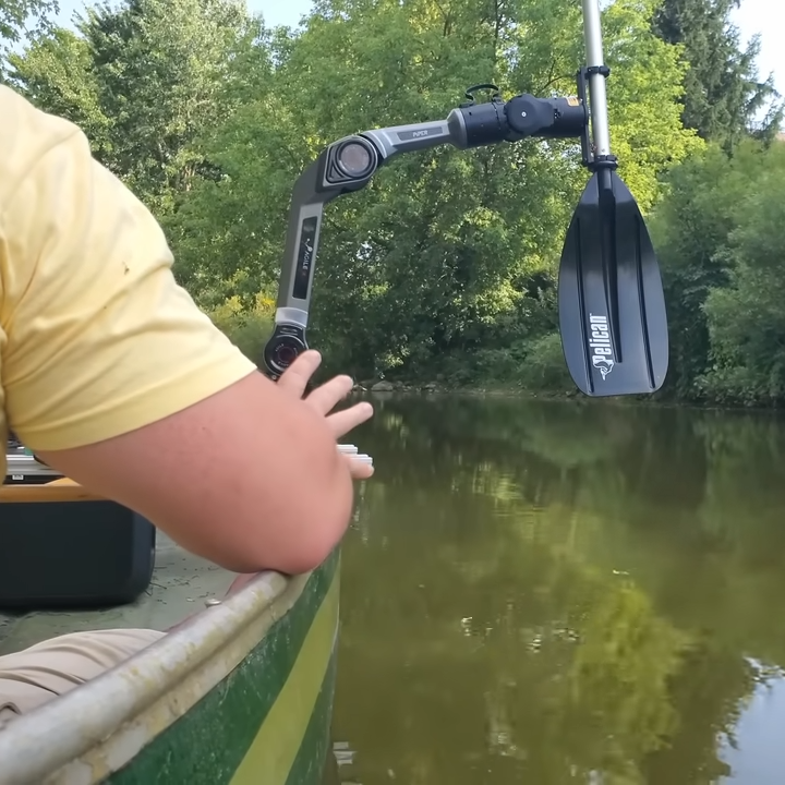
Most robots get around with tracks or wheels, but [Dave] had something different in mind. Sufficiently unbothered by the prospect of mixing electronics and water, [Dave] augmented a canoe with twin, paddle-bearing robotic arms to bring to life a concept he had: the RowboBoat. The result? A canoe that can paddle itself with robotic arms, leaving the operator free to take a deep breath, sit back, and concentrate on not capsizing.
There are a couple of things we really like about this build, one of which is the tidiness of the robotic platform that non-destructively attaches to the canoe itself with custom brackets. A combination of aluminum extrusion and custom brackets, [Dave] designed it with the help of 3D scanning the canoe as a design aid. A canoe, after all, has nary a straight edge nor a right angle in sight. Being able to pull a 3D model into CAD helps immensely in such cases; we have also seen this technique used in refitting a van into an off-grid camper.
The other thing we like is the way that [Dave] drives the arms. The two PiPER robotic arms are driven with ROS, the Robot Operating System on a nearby Jetson Orin Nano SBC. The clever part is the way [Dave] observed that padding and steering a canoe has a lot in common with a differential drive, which is akin to how a tank works. And so, for propulsion, ROS simply treats the paddle-bearing arms as though they were wheels in a differential drive. The arms don’t seem to mind a little water, and the rest of the electronics are protected by a pair of firmly-crossed fingers.
The canoe steers by joystick, but being driven by ROS it could be made autonomous with a little more work. [Dave] has his configuration and code for RowboBoat up on GitHub should anyone wish to take a closer look. Watch it in action in the video, embedded below.
In late 2024 Microsoft removed support for WMR (Windows Mixed Reality), and they didn’t just cease development. As of Windows 11 version 24H2, headsets like the HP Reverb and others by Acer, Samsung, Lenovo, and Dell stopped working at all. But the good news is developer [Matthieu Bucchianeri] created the Oasis driver for Windows Mixed Reality which allows WMR headsets (and their controllers) to work again.
Oasis is available as a free download from Steam and involves a few specific setup steps in order to get working, but once the headset and controllers are unlocked and room setup is complete, the hardware will be usable again. Note that while SteamVR is handy, one’s headset and controllers are not actually tied to SteamVR. Any VR application that uses OpenVR or OpenXR should work.
It’s an extremely well-documented project, and anyone willing to read and follow a short list of directions should be off to the races in no time.
Now that there’s a way for folks to dust off their WMR hardware and get back in the game, it’s a good time to mention that if you have ever suffered from VR sickness, we’ve covered ways to help deal with and adapt to it.
3D prints destined for presentation need smooth surfaces, and that usually means sanding. [Uncle Jessy] came across an idea he decided to try out for himself: spraying Bondo spot putty onto a 3D print. Bondo spot putty comes from a tube, cures quickly, and sands smoothly. It’s commonly used to hide defects and give 3D prints a great finish. Could spraying liquified Bondo putty onto a 3D print save time, or act as a cheat code for hiding layer lines? [Uncle Jessy] decided to find out.
Gaps and larger flaws still need to be filled by hand, but spray application seems to be a big time saver if nothing else.
The first step is to turn the distinctive red putty into something that can be sprayed through a cheap, ten dollar airbrush. That part was as easy as squeezing putty into a cup and mixing in acetone in that-looks-about-right proportions. A little test spray showed everything working as expected, so [Uncle Jessy] used an iron man mask (smooth surfaces on the outside, textured inside) for a trial run.
Spraying the liquified Bondo putty looks about as easy as spraying paint. The distinctive red makes it easy to see coverage, and it cures very rapidly. It’s super easy to quickly give an object an even coating — even in textured and uneven spots — which is an advantage all on its own. To get a truly smooth surface one still needs to do some sanding, but the application itself looks super easy.
Is it worth doing? [Uncle Jessy] says it depends. First of all, aerosolizing Bondo requires attention to be paid to safety. There’s also a fair bit of setup involved (and a bit of mess) so it might not be worth the hassle for small pieces, but for larger objects it seems like a huge time saver. It certainly seems to cover layer lines nicely, but one is still left with a Bondo-coated object in the end that might require additional sanding, so it’s not necessarily a cheat code for a finished product.
If you think the procedure might be useful, check out the video (embedded below) for a walkthrough. Just remember to do it in a well-ventilated area and wear appropriate PPE.
Some readers may recall the Lynx-R1 headset — it was conceived as an Android virtual reality (VR) and mixed reality (MR) headset with built-in hand tracking, designed to be open where others were closed, allowing developers and users access to inner workings in defiance of walled gardens. It looked very promising, with features rivaling (or surpassing) those of its contemporaries.
The unusual optics are memorable. (Hands-on Lynx-R1 by Antony Vitillo)
As a headset the Lynx-R1 had a number of intriguing elements. The unusual optics, the flip-up design, and built-in hand tracking were impressive for its time, as was the high-quality mixed reality pass-through. That last feature refers to the headset using its external cameras as inputs to let the user see the real world, but with the ability to have virtual elements displayed and apparently anchored to real-world locations. Doing this depends heavily on the headset being able to track its position in the real world with both high accuracy and low latency, and this is what ORB-SLAM3 provides.
A successful crowdfunding campaign for the Lynx-R1 in 2021 showed that a significant number of people were on board with what Lynx was offering, but developing brand new consumer hardware is a challenging road for many reasons unrelated to developing the actual thing. There was a hands-on at a trade show in 2021 and units were originally intended to ship out in 2022, but sadly that didn’t happen. Units still occasionally trickle out to backers and pre-orders according to the unofficial Discord, but it’s safe to say things didn’t really go as planned for the R1.
It remains a genuinely noteworthy piece of hardware, especially considering it was not a product of one of the tech giants. If we manage to get our hands on one of them, we’ll certainly give you a good look at it.
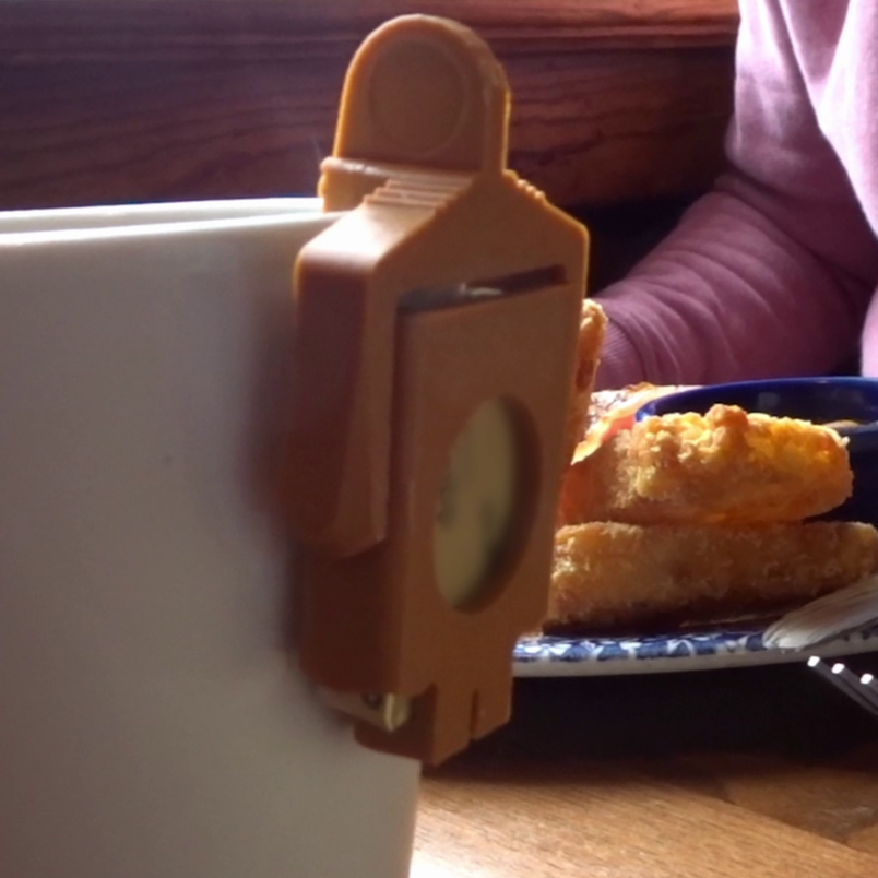
Ever ruin a perfectly serviceable piece of toast by trying (and failing) to spread a little pat of rock-solid butter? [John Dingley] doesn’t! Not since he created the Butta Melta to cozily snug a single butter serving right up against a warm beverage, softening it just enough to get nice and spreadable. Just insert one of those foil-wrapped pats of butter into the Melta, hang its chin on the edge of your mug, and you’ll have evenly softened butter in no time.
The Butta Melta is intentionally designed with a bit of personality, but also has features we think are worth highlighting. One is the way it’s clearly designed with 3D printing in mind, making it an easy print on just about any machine in no time at all. The second is the presence of the hinge point which really helps the Butta Melta conform to a variety of cup designs, holding the payload as close as possible to the heat regardless of cup shape. A couple of minutes next to a hot beverage is all it takes for the butter to soften enough to become easily spreadable.
You may remember [John] (aka [XenonJohn]) from his experimental self-balancing scooters, or from a documentary he made about domestic ventilator development during COVID. He taught himself video editing and production to make that, and couldn’t resist using those skills to turn a video demo of the Butta Melta into a mock home shopping style advertisement. Watch it below, embedded just under the page break, then print one and save yourself from the tyranny of torn toast.