As a British voter with some interest in the matter, I decided to write to my Member of Parliament about it, and since my letter says what I would have written to cover the story anyway it stands below in lieu of the normal Hackaday article format. If you are a British multirotor flier this is an issue you need to be aware of, and if you have any concerns you should consider raising them with your MP as well. Continue reading “The British Drone Law Reaches Parliament”→
A few months ago the Raspberry Pi magazine The MagPi gave away a piece of hardware, the Google AIY voice control kit. Subscribers all received one, but as always the eBay scalpers cleaned up all the in-store copies and very few lucky enthusiasts scored a kit of their own.
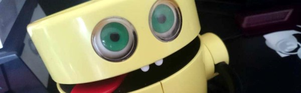
Among these frustrated Pi owners was [Circuitbeard], who decided instead to make his own kit. And since a cardboard case lacked style, he decided to do so in the shell of a 1980s Tomy Mr. Money toy novelty bank. Into it went a Raspberry Pi Zero W and an audio pHat, with a servo to operate the head and a microswitch connected to the toy’s arm as a trigger.
The Python code to run everything is all included in the write-up, and he’s posted a video of the device in operation which we’ve placed below the break.
If you have ever been to a hacker camp, you’ll know the problem of transporting all your stuff to your hackerspace village, or to wherever you’ll be basing yourself for the duration. The car park is always too far away, whatever trolley you’ve brought along is never big enough, and the terrain you have to drag everything over feels more like the Chilkoot Trail than a city sidewalk.
[Jana Marie Hemsing] and [Lucy Fauth] have an effective solution to all your hacker camp transport woes, in the form of a motorized platform designed to carry a storage box. Underneath the platform are a pair of hoverboard motors and their controller board reflashed with a custom firmware.
You might be now looking at it and thinking “So what?”, for a single platform is handy but hardly a comprehensive transport solution. What makes this one impressive though is that it’s not a single board, instead there is a swarm of them for which they appear to have implemented some form of optical following system which is teased through the video we’ve placed below the break and with this Tweet, but not in detail yet in the wiki page. A neat train of platforms follows the lead one, transporting everything with minimum fuss. What can we say, except “We want one too!”. There is some code to be found in a GitHub repository, should you be interested in having a go for yourself.
A popular purchase from the usual stockists of imported electronic modules is a digital panel meter. A very small amount of money secures a module with a seven-segment display that you can stick on the front of your power supply or project for an easy readout. Even before the advent of these ultra-cheap Chinese products there have been readily available digital meters, in a line stretching back to the 1970s with chips such as the Intersil 7106.
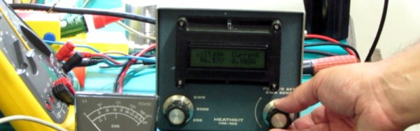
[Marcus Taciuc] is eschewing the off-the-shelf parts, and creating his own digital panel meter. He’s using an MSP430 microprocessor as the brain of his device, and a Hitachi HD44780 compatible LCD display at the front end. The appropriate combinations of resistors and op-amps feeding the MSP’s ADC inputs allow his meter to be used to measure up to 40 VDV, and up to 10A.
He’s put up a video which we’ve included below the break, showing the use to which this meter has been put: replacing the moving-coil meter in what looks like a classic piece of Heathkit equipment. A 3D printed bracket allows the new meter to fit the circular hole of the original meter, with the LCD on the front. You might still order a prefab meter module, but you can’t deny this looks good.
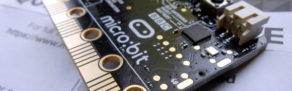
The BBC micro:bit has been with us for about eighteen months now, and while the little ARM-based board has made a name for itself in its intended market of education, we haven’t seen as much of it in our community as we might have expected.
If you or a youngster in your life have a micro:bit, you may have created code for it using one of the several web-based IDEs, a graphical programming system, TypeScript, or MicroPython. But these high level languages are only part of the board’s software stack, as [Matt Warren] shows us with his detailed examination of its various layers.
The top layer of the micro:bit sandwich is of course your code. This is turned into a hex file by the web-based IDE’s compiler, which you then place on your device. Interestingly only the Microsoft TypeScript IDE compiles the TypeScript into native code, while the others bundle your code up with an interpreter.
Below that is the micro:bit’s hardware abstraction layer, and below that in turn is ARM’s Mbed OS layer, because the micro:bit is at heart simply another Mbed board. [Matt] goes into some detail about how the device’s memory map accommodates all these components, something essential given that there is only a paltry 16 kB of RAM in hand.
You might wish to program a micro:bit somewhat closer to the metal with the Mbed toolchain, but even if that is the case it’s still of interest to read a dissection of its official stack. Meanwhile, have a look at our review of the board, from summer 2016.
Yes, I really did print this the day before the story broke.
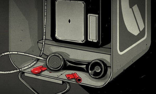
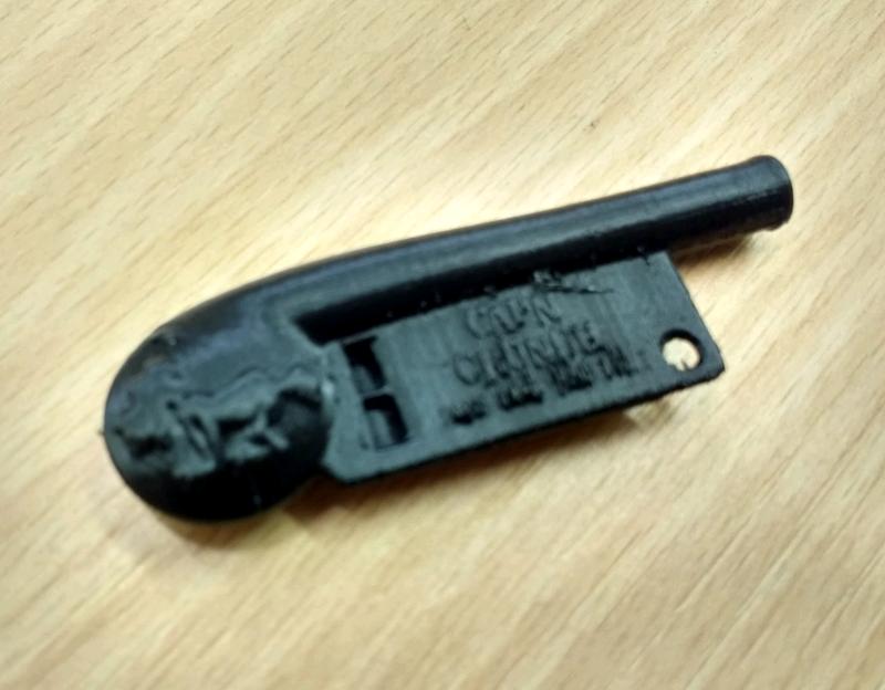
With hindsight, I picked the wrong day to 3D print a Cap’n Crunch whistle downloaded from Thingiverse. I was covering the hackspace textile evening, so I set the Ultimaker going and headed off to spend my evening making a laptop pouch. My whistle, a reasonable reproduction of the famous cereal packet novelty whose 2600 Hz tone allowed special access to American telephone networks, was ready for me to take away as I headed home.
The next day, there it was. The legendary phreaker [John Draper], also known as [Captain Crunch] after his use of that free whistle, was exposed as having a history of inappropriate conduct towards teenage boys and young men who he encountered in his tours of the hacker community as a celebrity speaker.
My whistle will no longer go on a lanyard as a piece of cool ephemera, it’s sitting forlornly on my bench. The constant procession of harassment allegations that have been in the news of late have arrived at our doorstep. Continue reading “We Need To Have A Chat About Something Important”→
Printed circuit boards are a fundamental part of both of commercial electronic equipment and of the projects we feature here on Hackaday. Many of us have made our own, whether done so from first principles with a tank of etchant, or sent off as a set of Gerbers to a PCB fab house.
To say that the subject of today’s Retrotechtacular is the manufacture of printed circuit boards might seem odd, because there is nothing archaic about a PCB, they’re very much still with us. But the film below the break is a fascinating look at the process from two angles, both for what it tells us about how they are still manufactured, and how they were manufactured in 1969 when it was made.
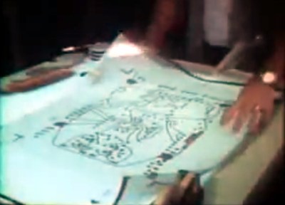
Board artwork laid out at four-times actual size
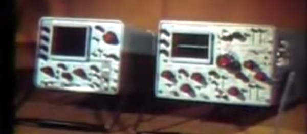
Tektronix were as famous for the manufacturer of particularly high quality oscilloscopes back then as they are now. The Tektronix ‘scopes of the late 1960s featured several printed circuit boards carrying solid-state electronics, and were manufactured to an extremely high standard. The film follows the manufacturing process from initial PCB layout to assembled board, with plenty of detail of all production processes.
In 2017 you would start a PCB design in a CAD package, but in 1969 the was incredibly manual. Everything was transcribed by hand from a paper schematic to transparent film. Paper mock-ups of component footprints four times larger than actual size are placed on a grid, and conductors drawn in pencil on an overlaid piece of tracing paper. Then the pads and pattern of tracks are laid out using black transfers and tape on sheets of film over the tracing paper, one each for top and bottom of the board. A photographic process reduces them to production size onto film, from which they can be exposed and etched in the same way that you would in 2017.
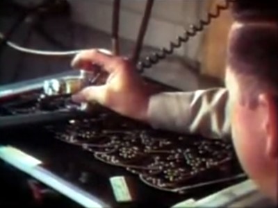
Pantograph drilling machine uses a manually moved styuls on a template to drill six boards at once
Most of the physical process of creating a PCB has not changed significantly since 1969. We are shown the through-plating and gold plating processes in detail, then the etching and silkscreening processes, before seeing component installation and finally wave soldering.
What are anachronistic though are some of the machines, and the parts now robotised that were done in 1969 by hand. The PCB drilling is done by hand with a pantograph drill for small runs, but for large ones a fascinating numerically-controlled drilling rig is used, controlled by punched tape without a computer in sight. Component placement is all by hand, and the commentator remarks that it may one day be done by machine.
The film remains simultaneously an interesting look at PCB production and a fascinating snapshot of 1960s manufacturing. It’s probable that many of the Tek ‘scopes made on that line are still with us, they’re certainly familiar to look at from our experience at radio rallies.