For some of those who are aficionados of the drink, tea making can be serious business. For them, strong, black, leaf tea left for ages to stew in a stained teapot that would strip the hairs off your chest (like it should be made) just won’t do. These beverage anarchists demand a preparation process of careful temperature regulation and timing, and for some reason repeatedly dunking a teabag in the water.
For them, [Dorian Damon] has an automated solution to getting the crucial dunking process right. He’s made an automatic tea bag dunker. The teabag is mounted on a slide operated by a crank, and the crank is driven through a pair of bicycle hubs. Motive power comes from a mains shaded-pole motor, an unusual bi-directional one of which he only uses one side. He measured his personal dunking rate at about 50 per minute, so he only needed a 4:1 reduction to match the motor at 200 RPM.
The resulting machine will happily dunk his tea bag at that rate for as long as it’s left switched on. He’s put a few videos up, of which we’ve posted one below the break.
A huge number of modern replicas of retro computers pass our screens here at Hackaday, and among them are an astonishing variety of technologies. Those who weren’t lucky enough to be present in the days when the building blocks of computing were coming together may have missed out on understanding gate-level operation of a computer. Put your super-powerful and super-complex systems-on-chip aside sometime and dig into the details of their distant ancestors.
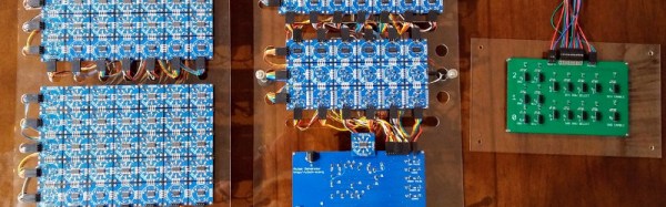
Most such machines follow a very conventional architecture, so it is something of a surprise to find a project recreating a modern version of something far more obscure. The Harwell Dekatron, also known as the WITCH, can be found at the National Museum Of Computing in Bletchley, UK, and [David Anders] is building a modern all-electronic replica of it.
The original machine is currently the world’s oldest working digital computer, a hybrid electromechanical computer built at the start of the 1950s to perform calculations for British nuclear scientists. It was retired by the end of that decade and found its way — via a technical college, a museum, and a period of storage in a council archive — to Bletchley where it was restored to working order by 2012. Its special feature is the use of dekatron discharge tubes as memory, allowing an instant visual display of its working as it happens.
[David]’s replica uses modern logic chips to replicate the building blocks of the Harwell Dekatron, and his write-up is as fascinating for that as it is for his study of the real thing in the museum. We ran into [Dave] showing off this project at the Hackaday Dallas event last year and are excited to learn of the advancements since then from his Hackaday.io page. He’s put his research and designs on GitHub, and a series of YouTube videos, the introduction to which we’ve put below the break.
You might think that if you have a need to measure the speed of a projectile that is too fast for your high-speed camera, you would have to invest in some significantly expensive equipment.
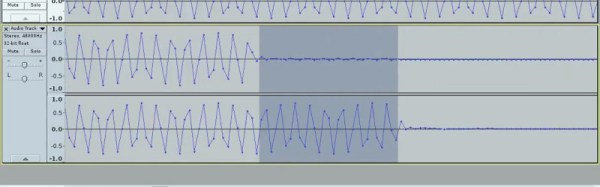
That was the problem facing [Nick Moore], and the solution he arrived at is extremely elegant in its simplicity. He’s arranged a pair of foil tapes in the path of the projectile, as it passes through them they break, and he measures the time between those breaks. The clever bit though lies not in the tapes, but in how he measures the timing. Instead of relying on a lab stuffed with equipment, he’s using his computer sound card. The outputs send a tone through each tape to the inputs, and using Audacity he can capture both tones and measure the time between the end of each one on left and right channels.
In the video below the break he demonstrates measuring the speed of a supersonic particle at 496.5 metres per second, which for such relatively simple equipment is rather an achievement. He could certainly improve his resolution by increasing the sampling frequency, but we are guessing that the choice of 48 kHz owes much to the quality of his sound card. Still, to achieve this with such a relatively basic piece of equipment is a neat achievement.
So often, 3D printer owners buy their machines with the promise of freeing themselves from the shackles of commercial manufactured items, and making all sorts of wonderful and useful things to improve their lives. Then they proceed to print a menagerie of good luck cats and toy elephants, that little tugboat, and a host of other pretty but ultimately useless items in garishly colored filament.
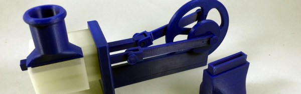
Perhaps this is an unfair assessment, but if you have the sneaking feeling that it might just describe you then could we point you at something that while it still has little use is at least interesting to play with. [Gzumwalt]’s single cylinder air engine is as its name suggests, a piston engine that runs on compressed air. You don’t need a shop compressor though, your lungs or an inflated balloon will suffice.
It’s a simple enough design, but it does incorporate two connecting rods, one of which drives a sliding valve. All the files are available for download, and there is a video we’ve placed below the break showing it chugging away nicely from a balloon. It might not be the most useful of engines and it may not bring you good luck, but it beats a plastic menagerie in the interest stakes.
If you were to nominate a technology from the 19th century that most defined it and which had the greatest effect in shaping it, you might well settle upon the railway. Over the century what had started as horse-drawn mining tramways evolved into a global network of high-speed transport that meant travel times to almost anywhere in the world on land shrank from months or weeks to days or hours.
For Brits, by the end of the century a comprehensive network connected almost all but the very smallest towns and villages. There had been many railway companies formed over the years to build railways of all sizes, but these had largely conglomerated into a series of competing companies with a regional focus. Each one had its own main line, all of which radiated out from London to the regions like the spokes of a wheel.
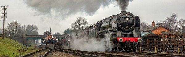
By the 1890s there was only one large and ambitious railway company left that had not built a London main line. The Great Central Railway’s heartlands lay in the North Midlands and the North of England, yet had never extended southwards. In the 1890s they launched their ambitious scheme to build their London connection, an entirely new line from their existing Nottingham station to a new terminus at Marylebone, in London.
Since this was the last of the great British main lines, and built many decades after its rivals, it saw the benefit of the century’s technological advancement. Gone were the thousands of navvies (construction workers, from “Navigational”) digging and moving soil and rock by hand, and in their place the excavation was performed using the latest steam shovels. The latest standards were used in its design, too, with shallow curves and gradients, no level crossings, and a wider Continental loading gauge in anticipation of a future channel tunnel to France This was a high-speed railway built sixty years before modern high-speed trains, and nearly ninety years before the Channel Tunnel was opened.
There was a time when the desktop peripherals such as your keyboard and mouse were expensive items that you hung on to and cared for. But several decades of PC commoditization and ever-cheaper manufacturing have rendered each of them to an almost throwaway level, they are so cheap that when one breaks you can simply reach for another without thought.
This is not to say that there is no longer a space for a more costly specialist keyboard. You’ll find enthusiasts still clinging to their treasured vintage IBM Model Ms and Model Fs, or typing on a range of competing high end ‘boards. You might say that a cheap keyboard is pretty high quality these days, but for some people only the feel of a quality switch will do.
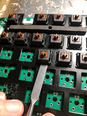
[Mac2612] was given a particularly nice example of this class of peripheral, a Das Keyboard 4C complete with trademark missing key decals. There was a snag though, it has suffered a spill at some time in its life, and would issue random keypresses which rendered it useless. His marathon investigation and repair of the fault makes for an interesting read, and gives us some insight into why these keyboards cost the extra money.
“To my dismay, I quickly realized that this was probably an unnecessary endeavor…”
At first it seemed as though corrosion on the board might be the issue, so he gave it a clean with IPA. All to no avail, and so began a succession of further dismantlings and cleanups which culminated in the desoldering of all the key switches. This lengthy task shows us in detail the construction of a high-end ‘board, but sadly it didn’t reveal the fault, and phantom keypresses kept appearing.
Following the board traces back to the microcontroller, he eventually found that moisture had corroded the end of a 10K surface mount resistor, leaving it with a resistance in the MOhms. Since it was a pulldown for one of the keyboard rows, he’d found the source of the problem. Having spent a long time fault-finding a board with an SMD part with a mechanical failure, we feel his pain.
Replacing the SMD parts and reassembly gave him a rather sweet keyboard, albeit for a lot of work.
To a radio amateur who received their licence decades ago there is a slightly surreal nature to today’s handheld radios. A handheld radio should cost a few hundred dollars, or such was the situation until the arrival of very cheap Chinese radios in the last few years.
The $20 Baofeng or similar dual-bander has become a staple of amateur radio. They’re so cheap, you just buy one because you can, you may rarely use it but for $20 it doesn’t matter. Most radio amateurs will have one lying around, and many newly licensed amateurs will make their first contacts on one. They’re not even the cheapest option either, if you don’t mind the absence of an LCD being limited to UHF only, then the going rate drops to about $10.
The Baofengs and their ilk are great radios for the price, but they’re not great radios. The transmitter side can radiate a few too many harmonics, and the receivers aren’t the narrowest bandwidth or the sharpest of hearing. Perhaps some competition in the market will cause an upping of the ante, and that looks to be coming from Xiaomi, the Chinese smartphone manufacturer. Their Mijia dual-band walkie-talkie product aims straight for the Baofeng’s jugular at only $35, and comes in a much sleeker and more contemporary package as you might expect from a company with a consumer mobile phone heritage. Many radio amateurs are not known for being dedicated followers of fashion, but for some operators the sleek casing of the Mijia will be a lot more convenient than the slightly more chunky Baofeng.
This class of radio offers more to the hardware hacker than just an off-the-shelf radio product, at only a few tens of dollars they become almost a throwaway development system for the radio hacker. We’ve seen interesting things done with the Baofengs, and we look forward to seeing inside the Xiaomi.
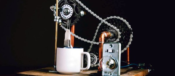
 For them, [Dorian Damon] has an automated solution to getting the crucial dunking process right. He’s made an automatic tea bag dunker. The teabag is mounted on a slide operated by a crank, and the crank is driven through a pair of bicycle hubs. Motive power comes from a mains shaded-pole motor, an unusual bi-directional one of which he only uses one side. He measured his personal dunking rate at about 50 per minute, so he only needed a 4:1 reduction to match the motor at 200 RPM.