If you need to generate a radio frequency electrical signal, you will make some form of electronic oscillator. We’ll probably all be used to oscillators using transistors, tubes, logic gates or a host of other electronic technologies. Similarly if you need to generate radio frequencies at high powers, you’ll couple your oscillator to an amplifier, a relatively simple task with today’s electronic parts bin.
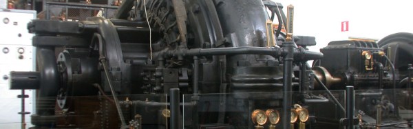
If you needed to do the same thing with a high power radio signal in the early years of the 20th century, none of these options were open to you. There were no transistors or integrated circuits, and the tubes of the day could not produce high power outputs. Radio engineers back then had to employ other solutions to the problem, one of which was the Alexanderson alternator. It’s old news we’ve covered here before at Hackaday, a high frequency alternator capable of generating hundreds of kilowatts in the VLF radio frequency range.
There is one operational Alexanderson alternator remaining in the world at the Varberg radio station at Grimeton in Sweden. It is no longer in constant use, but as a World Heritage Site and museum it is put on air a few times a year including the Sunday closest to the 2nd of July, known as Alexanderson Day. We come now to the point of this article: this year’s 3rd of July Alexanderson Day transmission is fast approaching, and since last time we covered it we signed off with a plea for a good VLF antenna design we should post a solution in good time to allow our readers to receive this year’s signal.
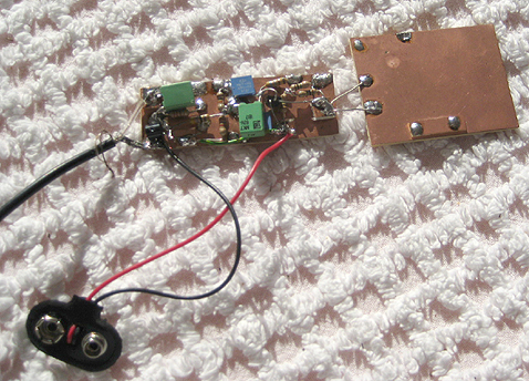
Fixing up a receiver is easy enough, we linked to the original SAQrx VLF Receiver and the extended version in our previous coverage. Both pieces of software use your computer’s sound card as the front end of a software defined radio to receive the 17.2kHz from Grimeton. The antenna though presents a problem. You might think that attaching a long piece of wire to the microphone input would be enough, but the problem is that due to the huge wavelength of the VLF signal any reasonable long wire you might be able to assemble simply wouldn’t be long enough to deliver a good result. Clearly a different antenna is required, and the solution comes courtesy of a high-impedance active e-field antenna. This uses a FET input and a surprisingly small patch antenna to deliver a low noise floor at VLF frequencies rather than to be the amplifier you might expect.
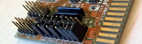
We’ve found a couple of designs for you to look at. The first is a two transistor version you will find in various different guises on many sites. This one uses an MPF102 FET, but you should be able to substitute a J310. The second design is a little more surprising, while it is the same idea of a FET input amplifier it uses a TL071 op-amp as its active device. This is in no way an IC you’d normally expect to find in an RF circuit, however the frequency in question is not that of your normal RF.
If you build either of these antennas we hope you’ll be able to hear the Alexanderson Day transmission. The point of a high power VLF transmitter is that it has a huge coverage area, so it should be possible to receive it across all of Europe and perhaps into the eastern United States. If you are out of range though, never fear. You can always try to pick it up through a handy webSDR receiver closer to the source.
Alexanderson alternator picture By Gunther Tschuch (Own work) [ CC BY 2.5 ], via Wikimedia Commons.
![Different capacitor applications. By Elcap (Own work) [CC0], via Wikimedia Commons](https://hackaday.com/wp-content/uploads/2016/06/capacitors-overlapping-applications.png)
![Can these logos really be trusted? By Moppet65535 (Own work) [CC BY-SA 3.0], via Wikimedia Commons](https://hackaday.com/wp-content/uploads/2016/06/fcc-ce-logos.jpg?w=400)