
Over on YouTube [Andrew Neal] has a Function Generator Build for Beginners.
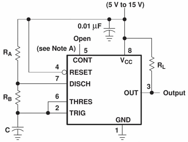 As beginner videos go this one is fairly comprehensive. [Andrew] shows us how to build a square-wave generator on a breadboard using a 555 timer, explaining how its internal flip-flop is controlled by added resistance and capacitance to become a relaxation oscillator. He shows how to couple a potentiometer to vary the frequency.
He then adds an integrator built from a TL082 dual op amp to convert the circuit to a triangle-wave generator, using its second op amp to build a binary inverter. He notes that a binary inverter is usually implemented with a comparator, but he uses the op amp because it was spare and could be put to good use. Again, potentiometers are added for frequency control, in this case a 1 MΩ pot for coarse control and a 10 kΩ pot for fine control. He ends with a challenge to the viewer: how can this circuit be modified to be a sine-wave generator? Sound off in the comments if you have some ideas!
If you’re interested to know more about function generators check out A Function Generator From The Past and Budget Brilliance: DHO800 Function Generator.
Continue reading “555-Based Square-Wave And Triangle-Wave Function Generator Build For Beginners”


![[nanofix] and his assortment of tweezers](https://hackaday.com/wp-content/uploads/2026/01/nanofix-tweezers-banner.jpg?w=600&h=450)


