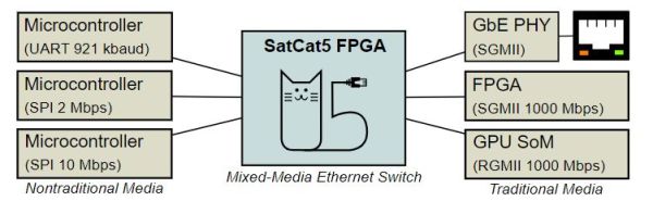
To the average microcontroller, Ethernet networks are quite a step up from the basic I2C, SPI and UART interfaces, requiring either a built-in Ethernet MAC or SPI-based MAC, with tedious translation between Ethernet and those other interfaces. Yet what if this translation could be done automatically and transparently? This is what the SatCat5 FPGA-based project by [The Aerospace Corporation] aims to provide: a gateway akin to an unmanaged Ethernet switch that also supports those non-Ethernet links. Recently they answered a range of questions about the project on Hacker News.
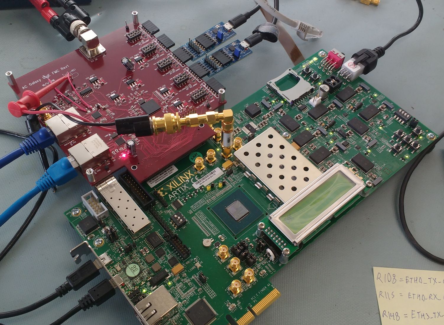
The project name comes from the primary target audience: smallsat and cubesat developers, which is an area where being able to route more traffic over a common Ethernet-based bus is a major boon. The provided Xilinx Artix-7-based reference design (pictured) gives a good idea of how it can be used: it combines an Arty A7 development board with a custom PCB containing an Ethernet switch IC (SJA1105), TJA1100 transceiver, two RJ45 jacks and four PMOD connectors, here connected to two UARTs for bidirectional communication between them. Ethernet frame encapsulation is provided using the standard Serial Line Internet Protocol (SLIP), with more details covered in the FAQ. At a minimum an FPGA like a Lattice iCE40 is required, with an MCU capable of using the provided C++ libraries, or a custom implementation.
Thanks to [STR-Alorman] for the tip.