Build A Bare Bones Arduino Clone Which Maximizes Its Use Of Real Estate

barebones-arduino-clone-at-home

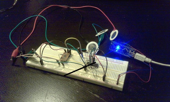
Check out all the stuff crammed into a small swath of strip board. It’s got that characteristic look of a roll-your-own Arduino board, which is exactly what it is. [S. Erisman] shows you how to build your own copy of his YABBS; Yet Another Bare Bones Arduino (on Stripboard).

The strips of copper on the bottom of the substrate run perpendicular to the DIP chip and have been sliced in the middle. This greatly reduces the amount of jumpering that would have been necessary if using protoboard. A few wires make the necessary connections between the two tooled SIL headers that make up the chip socket. On the right hand side there a voltage regulator with smoothing caps. The left side hosts the obligatory pin 13 LED, and the crystal oscillator can be glimpsed on the far side of the ATmega328.

Pin headers along either side of the board have been altered to allow for soldering from the wrong side of the plastic frames. Note that there’s a three-pin hunk that breaks out the voltage regulator, and an ISP programming header sticking out the top to which those female jumper wires are connected.

Ringing in at as little as $2-$4.75 a piece you’ll have no problem leaving this in a project for the long hall. We can’t say the same for a $30+ brand name unit.

Ambilight Clone Uses Video Pass-through; Needs No Computer

To the best of our knowledge all of the Ambilight clones we’ve covered over the years have one thing in common. They need a computer to do the image processing. This one is different. The PCB seen on the left right is all you need for the video processing. The project is called SCIMO and is the handiwork of a hacker named [Keiang].

There are only few times that the DRM built into the HDMI standard has pissed us off. This is one of them. Because of HDCP and licensing issued revolving around HDMI [Keiang] didn’t use HDMI pass through. Instead he uses an HDMI to S-Video converter. This board acts as an S-Video pass through, analyzing the signal using an STM32 ARM chip before the video signal continues on to the television. It still produces a respectable picture, but wouldn’t it have been cleaner if he could have gone with the HDMI standard?

UPDATE: Thanks for the comments on this. It looks like the TV is getting an HDMI signal. The board is fed by the HDMI to S-Video converter which itself is getting HDMI in parallel with the television thanks to a splitter.

Where other examples use Boblight on a PC for processing this manages to do so as a standalone embedded system. It also offers quite a bit of flexibility when it comes to choosing the LEDs, supporting pixels that use DMX512, WS28xx, or TM18xx protocols.

Continue reading “Ambilight Clone Uses Video Pass-through; Needs No Computer”

24-hour Hackathon Project Adds Object-based Automation To Hackerspace

hackerspace-automation

[Jeremy Blum], [Jason Wright], and [Sam Sinensky] combined forces for twenty-four hours to automate how the entertainment and lighting works at their hackerspace. They commandeered the whiteboard and used an already present webcam as part of their project. You can see the black tokens which can be moved around the blue tape outline to actuate the controls.

MATLAB is fed an image from the webcam which monitors the space. Frames are received once every second and parsed for changes in the tokens. There are small black squares which either skip to the next track of music or affect pause/play. Simply move them off of their designated spot and the image processing does the rest. This goes for the volume slider as well. We think the huge token for the lights is to ensure that the camera can sense a change in a darkened room.

If image processing isn’t your thing you can still control your audio entertainment with a frickin’ laser.

Continue reading “24-hour Hackathon Project Adds Object-based Automation To Hackerspace”

Best Practices To Include In Your Final Projects

electronic-best-practices

Making that final push to button up your projects can be a bit daunting. It’s kind of like the punch list on a construction project — add switch plates, fill nail holes in baseboards, screw in light bulbs, clean windows — that stuff adds up quickly. But having a set of best practices in mind throughout the development phase will cut down on that burden. [Caleb P.] just published a quick guide using a recent project as an example.

First and foremost is the label seen on the project box lid. How many times have you pulled out a circuit board from a year or two earlier and not been able to figure out the pinout? As with ancient televisions and radios, including the service schematic will save you big time! He also mentions that the size and orientation of the components in the case was in the back of his mind the whole time. That paid off because everything fits like a glove. [Caleb] makes sure the battery is easy to get to, and the each component has some type of connector so that it may be removed and serviced/replace without soldering. There’s certainly nothing groundbreaking in this guide. But ask yourself: have I been following all of these guidelines in my own work?

Hack It: In-refrigerator Egg Monitoring

Here’s a concept piece that monitors the eggs in your refrigerator. It’s still in development and we don’t think the general public is ready for digital egg monitoring quite yet. But we love the concept and want to hear from you to see if you could develop your own version.

What we know about the device is that — despite the image which makes smart phone proximity seem important — it connects to the Internet from inside your fridge. It will tell you how many eggs you have left, and even tracks the date at which each entered your refrigerator.

So, what’s inside this thing and who can build their own the fastest? We’ll cover some specs and speculate a bit to get you started: There’s a light sensor to detect when the door opens and an LED below each egg to illuminate the oldest. We think the light sensor triggers a microcontroller that uses each of the egg LEDs as a light sensor as well. If the threshold is too low then there is indeed an egg in that cup. We also like the fact that the tray has fourteen slots; as long as you don’t buy eggs until you have just two left you’ll always have room.

If you build one we want to know. We’re thinking 3D printed cups, low-power microcontroller, but we’re kind of stumped on the cheapest WiFi solution. Leave your thoughts in the comments.

[via Reddit via NY Daily News via Mind of Geek]

A Handful Of Parts Used To Form An Electrocardiogram

minimal-ecg

It’s difficult to image a more bare-bones approach to building an ECG. [Raul] used an Arduino nano to collect samples and push them to a computer for graphing.

An Electrocardiogram measures electrical activity around your heart. The white circles above are the sensors which he picked up in a box of fifty for 11 Euros (under $15). Stick them on your skin in just the right places and they’ll report back on what your heart is doing.

He used a AD8221 to amplify the signals. He mentions that this is an ins-amp, not an op-amp. We didn’t find a concise reference explaining what that is. It might be a good topic for the comments section. The signal from that chip feeds into an LM324 op-amp before being dumped into the Arduino.

Simplicity comes at a price. This measures very small electrical impulses and has very little in the way of shielding and filtering. Because of this you may need to do a rain dance, say a prayer, burn a candle, and stick needles into a doll to get a reliable signal on the other end.

Here’s another version that doesn’t require special sensors.

This Is Run By An Arduino

Let us be the first to say: Not a hack! Nonetheless this is an interesting read about how the Arduino movement has made hobby microcontroller boards attractive for industrial applications.

This is a digital printing machine which looks like it is used for industrial packaging. [Paul Furley] worked for the company which produces it, developing the software for the control interface. He recounts the story of how he helped guide the company away from choosing a microcontroller, and toward using an Arduino board. Actually, using three Arduino boards. We can already hear the flame war boiling up in the comments section. But before you rage, read the article and see if you don’t agree with [Paul’s] reasoning.

The most compelling argument to us is that choosing Arduino is absolutely future proof. If the company goes out of business there are hundreds of clone devices already available. As the Arduino platform evolves it will keep pin compatibility in order to support the older shields. And if they choose a different microcontroller the Arduino IDE will still compile the same sketch for the new hardware.

One thing that pops into our minds is write protection. The machine uses a big PCB to which the three Arduinos mount. That can be produced anywhere without threat of having the source code leak as the PCB doesn’t include chips that need to be programmed. Arduino uses AVR chips that have write protection fuses which can be burnt in-house after they flash the control firmware.

[Thanks Thomas]