Using An Arduino To Measure Inductance

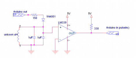
Measuring an inductor is not something that most multi-meters can do. You usually need a high precision resistor (1% or better) in series with the inductor, a function generator to put a signal through the circuit, and an oscilloscope to measure the result. But what can you do if you don’t have these tools on hand? [Andrew Moser] has a method that lets you pull it off with an Arduino and an LM339 quad comparator.

The circuit works by feeding a signal in from the Arduino. This waveform is affected by the LC circuit, filtered by the comparator chip, then read back out the other side by the Arduino. That resulting signal is a square wave, which is an easy target for the Arduino to measure. That timing measured from the square wave can then be used to calculate the inductor’s value.

This is quite handy if you’re winding your own inductors. Now you can precisely tune that Joule Thief you’ve been working on.

[via Dangerous Prototypes and Adafruit]

Creating Music From GPU Noise

Yep, that’s a picture of a Laptop rocking out on an electric guitar. In what can only be described as a truly bizarre hack [CNLohr] discovered that the RF noise from the computer can be used to play music through the guitar’s pickup.

Check out the clip after the break to hear an annoying, but very discernible rendition of Jingle Bells. Once [CNLohr] stumbled onto the fact that changes in what the graphic processing unit is doing was affecting the pitch detected by the pickup he started writing some code. Now he’s got a program that automatically calculates the size of the window, and produces a white square on a black background to dial in the GPU at the right frequencies.

He mentions in the notes accompanying his video that he had to turn off Vsync to get this to work right. We don’t understand why but we’d love to hear what you think in the comments.

Continue reading “Creating Music From GPU Noise”

Cypherbot Uses Older UC And Retro-controller

[PJ Allen] has been working on a little robot which he calls Cypherbot. The control circuitry is quite familiar; a Board of Education which features the Basic Stamp 2 microcontroller. This is an older and slower microprocessor, but it works quite well for this application since there’s no need for speed or heavy number crunching. The wheels of the bot are made out of plastic lids (we’re thinking peanut butter jars) with rubber bands for traction that are each driven by a servo motor. The third wheel is tiny and swivels as needed.

The front of the bot has a PING ultrasonic sensor mounted on a servo motor which lets the bot scan back and forth for a wider obstacle avoidance angle. In addition to the autonomous mode there’s an Xbee remote control. [PJ] picked up an Atari keyboard and is using that as the user input. Check out the little guy driving around the house in the video after the break.

Continue reading “Cypherbot Uses Older UC And Retro-controller”

Frustrating Fun With Magnetic Levitation

[Andrey Mikhalchuk] built his own magnetic levitation device and you can too… if you have the patience. He’s not using electromagnets, like the Arduino levitator or the floating globe. Instead, a pair of ceramic ring magnets and a few hours are all it takes.

The base of his device is a couple of very large ring magnets that would most often be used in speakers. It’s hard to see them in the image above because there’s an inverted plastic container obscuring them. A second (or third depending on how you’re counting) ring magnet is selected because it is smaller than the circular void in the magnetic base. It’s impossible to simply balance the magnet in the air, but spinning it is a different story. By creating a perfectly balance magnetic top, then spinning it inside the magnetic field of the base, you can leave it floating in mid-air.

Check out the video after the break. It’s a neat effect, but you really do have to have a perfect setup for it to work. [Andrey] mentions that it takes a couple of hours to fine-tune. And if the ambient conditions change slightly, it throws the whole thing off.

Continue reading “Frustrating Fun With Magnetic Levitation”

Adding Video Out To The Open Pandora

There’s very few users out there who actually have their hands on an Open Pandora Console. But the ones who do might find this hack useful for getting TV out up and running. It’s actually not hard at all, but if you don’t want to alter the hardware on the device you’ll first have to find a cable plug that will fit the EXT jack. This proved more difficult than it needed to be, since TI carries the connector but only sells them in multiples of 2200. A group buy was organized and we’d bet you can still get in on that action.

The connector in question carries TVout1 and TVout2 conductors. These correspond to the Luminance and Chrominance signals needed for the S-video protocol. But [MarkoeZ] wanted to use a composite connection. Turns out that’s not hard either, he hooked up the ground from the plug to the ground of the RCA jack, then connected both video lines to the center conductor, making sure to add an inline 470pf capacitor on the Chrominance side. Check out the demo video embedded after the break to see the final product.

Continue reading “Adding Video Out To The Open Pandora”

Using Binary Code Modulation To Control LED Brightness

Pulse Width Modulation is definitely the preferred method of dimming an LED with a microcontroller, but we were interested in hearing about a different method called Binary Code Modulation. BCM does the same thing as PWM, it turns the LED on and off very rapidly so that your eye cannot detect a flicker. The brightness level is a result of the average amount of time the LED is on versus when it is off. This is called duty cycle and although it can be the same percentage for both PWM and BCD, there is a fundamental difference.

While PWM usually uses a cyclical on/off cycle (30% on, 70% off, repeat) BCD uses a cumulative cycle. As you can see above, each successive bit of binary code carries double significance compared to the previous bit. Now just assign a duty cycle based on your precision, and have an interrupt fire for each bit of the counter. The graph above shows some highs and some lows combining to reach the target duty cycle. An interrupt is used for each bit, and pin changes are made in the service routine.

The benefit of this system is that it is scaleable without adding overhead. You’re already running the interrupts so servicing 8 or 128 LEDs doesn’t have vastly different needs as it would with PWM. The big downside is that the more bits of precision you use, the faster your processor must run so that the eye doesn’t detect the lengthy on or off cycles of the higher bits as visible flickering.

Thank you [Yetihehe] for tipping us off about a link that [Tomas Martinsen] left when commenting about an Arduino library for up to 768 PWM outputs.

Demystifying PID Control With A Look At The New Arduino PID Library

We’ve been hiding away in air-conditioned comfort to wait out the hot weather afflicting most of the US right now. Luckily we’re keeping busy with the great links coming into our tips box.

[Brett] sent us a note about his work on the new Arduino PID library. He is the author of the original library and recently decided it was time for a ground-up rewrite. But along the way he took the time to explain PID control and the choices he made during development.

We see a lot of PID controllers around here, like this router based espresso machine add-on. Proportional-Integral-Derivative Controllers are a way to make sure the control you intended to get from your devices is actually achieved in practice. They monitor a process and accumulate results over time in order to account for future events. From what we’ve just described you can see why the subject needs to be demystified.

Get yourself elbow-deep into [Brett’s] article. He does a great job of discussing each issue, and uses a multitude of easily understandable graphs to show the hurdles each portion of code is meant to overcome.