Re-manufacturing Inkjet Cartridges For 3d Printing


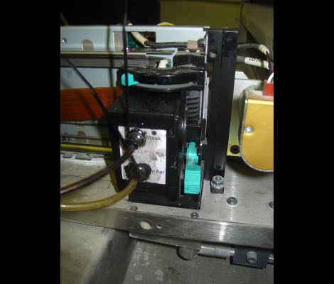
[Nullset] uses inkjet printer technology for his 3D printing needs. We usually think of hot-plastic printing like the RepRap or Makerbot when we hear about rapid prototyping, but this setup uses a liquid bonding agent to turn powder into a solid structure. Standard inkjet cartridges can be used to precisely place the bonding agent, but it’s hard on the heads and you have to replace them often. [Nullset] is getting pretty good at it, and decided to write a tutorial on the modifications necessary to print with bonding liquid.

At its core, the method injects binder into the cartridge through one port while using a second for drainage. [Nullset] found that the needle fittings used to inflate a basketball work great for this. He drills a couple of holes that the threaded end of the needles fit into. That connection is sealed with some epoxy, and the tubing that delivers the binder is zip-tied to the needles. A bit of purging is necessary to get rid of any old ink, but after the initial flush you’ll be up and running pretty quickly. He figures the whole process can be one in around 10 minutes once you get the hang of it.

Accounting For Material Loss When Laser Cutting


When you cut something out, you lose a bit of material in the process. Think of a table saw and the sawdust it produces, that’s the waste material lost in an area the width of the blade. It’s really easy to measure that, just measure the blade. But [James] started wondering about a good way to measure material loss from a laser cutter.

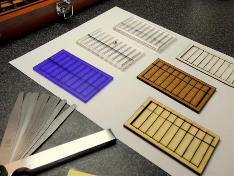
Why does it matter? If you’ve designed pieces that should fit together with each other, loss of material can lead to joints that aren’t tight. [James] figured out that the loss could be measured by making several cuts within a rectangular frame. You can see his test pieces above, with ten strips cut out of each frame. After the laser is done doing it’s work just slide all the pieces together and measure the opening created at one end. It helps to have an enhanced caliper to make the measurement easy to read. Now divide that distance by the number of laser passes and account for that dimension next time you design parts for the cutter.

Crafting A Hexapod With An RC Controller

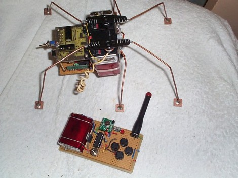
Here’s a fantastic project that lets to drive a hexapod around the room using an RC controller. [YT2095] built the bot after replacing the servo motors on his robot arm during an upgrade. The three cheapies he had left over were just begging for a new project, and he says he got the first proof-of-concept module put together in about an hour. Of course what you see above has gone through much improvement since then.

The three motors are epoxied together, with the one in the middle mounted perpendicular to the motors on either side of it. Those two are responsible for the front and rear leg on each side, with the third motor actuating the two middle legs. It’s a design we’re already familiar with having seen the smaller Pololu version. You might want to check that one out as there’s some slow motion video that shows how this works.

[YT2095] added control circuitry that includes an RF receiver. This lets him drive the little bot around using a transmitter with four momentary push switches on it. We love the idea of using copper clad for the foot pads.

Building A Stepper Driver

[TBJ] is building what he calls a junkbox 3D printer. You can probably guess that he’s trying to salvage most of the parts for the device, and after pulling a stepper motor from an old printer he was in need of a way to control it. What he came up with is a stepper driver that uses discrete components that are easy to acquire and inexpensive. The design calls for two inputs, one that toggles the direction in which the motor will spin, and the other that triggers one step of the motor. A CD4013 dual flip-flop takes care of both of these inputs in one chip package.

The motor is driven by a pair of H-bridges that he built using six transistors each. The trick with a stepper motor is that you need to drive the four poles of the motor to a specific logic level at a specific time. For this [TBJ] uses a CD4017 decade counter. A network of diodes grounds half of the output lines based on the flip-flop that controls direction. Our friend the 555 timer provides a clock for the circuit, keeping everything moving at a predefined rate. Check out the video after the break for an explanation and demonstration.

Continue reading “Building A Stepper Driver”

Waterfall Signal Visualizer From Arduino And Cellphone LCD

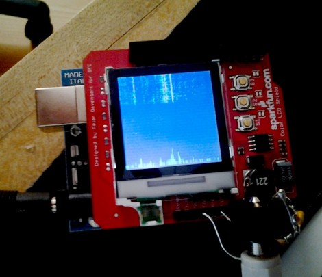
[Leigh] is a HAM operator (you may know him as wa5znu). He is familiar with a signal visualization tool called a waterfall which plots signal strength and frequency over time. He wanted to build his own waterfall and ended up with this Arduino-based version which he calls Cascata. Cascata means waterfall in Italian which meshes nicely with Arduino’s country of origin

The display he chose is a Nokia LCD shield from SparkFun. It’s easy to plug in and there were already libraries available to drive the display. The audio input just connects to a headphone plug (you can just make it out at the bottom right in the image above) using some electrical tape. A free-formed resistor divider ensures that the signal is within a measurable range. [Leigh] found that signal noise was a bit of a problem but was able to improve his results by adding a capacitor to the Arduino headers between the VREF and GND pins.

See it in action after the break.

Continue reading “Waterfall Signal Visualizer From Arduino And Cellphone LCD”

Repairing A Broken Salad Spinner

Behold [Quinn’s] broken salad spinner, and just when lettuce and other garden produce are hitting their peak. We were surprised to find out that she was able to get the mechanism apart to fix the broken cord. We’re sick and tired of ultrasonically welded plastic enclosures that lock out the most well-intentioned repairman. But in [Quinn’s] case there were a few plastic plugs hiding the screws that keep the two pieces of the case together.

After diagnosing that the cause of the broken cord was a gnarly metal grommet, she removed the offender and sought a replacement cord. The first material she tried was some dental floss but unsurprisingly it only lasted through a few spins. Next on the road to repair was a shoelace which did a bit better but also ended up broken. But the discovery of some parachute cord did the trick in the end and now it’s good as new if not better!

Hardware XOR For Output Pins On AVR Microcontrollers

Did you know that most AVR chips have a type of hardware exclusive OR (XOR) option when it comes to the logic levels of the output pins? If you look in the datasheet (the image above is a screenshot from an ATtiny13 datasheet) you’ll find a section on Toggling the Pin. It turns out that if you set a PORT as an output, writing logic one to the corresponding PIN register will toggle the logic levels of that out. This is really easy to overlook if you’re writing in C, but I’ve been working on learning a bit of assembler language and found this to be very useful. Keep reading after the break and I’ll tell you how I happened upon this info and what it’s good for.

Continue reading “Hardware XOR For Output Pins On AVR Microcontrollers”