A Web Connected Seismometer

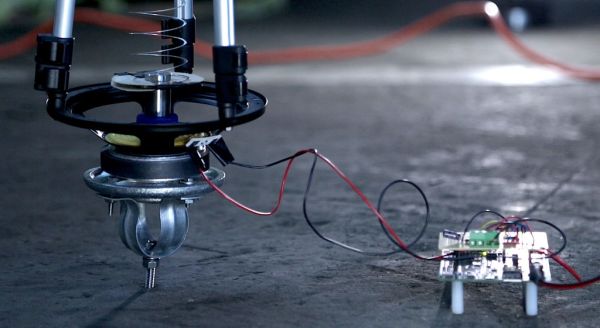
[10DotMatrix] has a budding interest in seismology, so she decided to make her own seismometer out of some easy-to-find materials. Seismometers are prohibitively expensive for hobbyists, but thankfully it’s really easy to build a usable siesmometer out of simple parts. [10DotMatrix]’s seismometer is built around a modified subwoofer, which acts as a transducer for the earth’s vibrations.

The subwoofer is mounted to the bottom of a tripod, which forms the structure of the seismometer. A slinky is stretched between the top of the tripod and a weight that rests on the coil of the subwoofer. Whenever the ground shakes, the slinky and weight vibrate and induce current in the voice coil.

Since these vibrations are usually quite small, the output of the subwoofer needs a bit of amplification. [10DotMatrix] fed the output of the woofer to an AD620 op amp, which amplifies the signal to a measurable level. The amplifier’s output is fed into an Intel Edison board, which samples the voltage and transmits it to a web dashboard for online viewing.

If you’re shaking with excitement about seismic measurements you’ll surely be interested in this similar method which uses a piezo element as the detector.

A Wooden LED Matrix Coffee Table

[johannes] writes in with a pretty impressive LED table he built. The table is based around WS2801 serially addressable LEDs which are controlled by a Raspberry Pi. The Pi serves up a node.js-driven web interface developed by [Andrew Munsell] for a room lighting setup. The web interface controls the pattern shown on the display and the animation speed.

[johannes] built a wooden coffee table around the LED matrix, which includes a matte glass top to help diffuse the lighting. An outlet to plug in a laptop and two USB charging ports are panel-mounted on the side of the enclosure, which are a nice touch. The power supply for the LEDs is also inside the enclosure, eliminating the need for an external power brick.

While [johannes] hasn’t written any software of his own yet, he plans on adding music synchronization and visualizations for weather and other data. Check out the video after the break to see the table in action.

Continue reading “A Wooden LED Matrix Coffee Table”

Home Automation Setup Keeps You Informed

[johannes] wrote in to tell us about his latest project, a home automation setup he named Botman. While he calls it a home automation system, controlling lights and home appliances (which it does wirelessly on 433MHz) is just a small part of its functionality. The front panel of Botman includes a servo which points to laser-etched icons of the current weather. It also has a display which shows indoor and outdoor weather conditions along with the status of public transportation around [johannes]’s house.

Botman is built around an Arduino with an Ethernet shield. The Arduino has very little memory, so [johannes] used the Google Apps engine as a buffer between his Arduino and the JSON APIs of his data sources. This significantly reduces the amount of data the Arduino has to keep in memory and parse.

[johannes] also wrote an Android app that communicates with Botman. The app has buttons for controlling lights in his house and duplicates all the information shown on the front panel. [johannes] also built some logging features into Botman. The temperature readings and other information are uploaded from the Arduino to a Google Docs spreadsheet where he can view and graph them from anywhere. Check out the video after the break to see Botman in action.

Continue reading “Home Automation Setup Keeps You Informed”

3D-Printed Clock Tells Time With Gears

[ekaggrat] designed a 3d-printed clock that’s fairly simple to make and looks awesome. The clock features a series of 3d-printed gears, all driven by a single stepper motor that [ekaggrat] found in surplus.

The clock’s controller is based around an ATtiny2313 programmed with the Arduino IDE. The ATtiny controls a Darlington driver IC which is used to run the stepper motor. The ATtiny drives the stepper motor forward every minute, which moves both the hour and minute hands through the 3d-printed gears. The hour and minute are indicated by two orange posts inside the large gears.

[ekaggrat] etched his own PCB for the microcontroller and stepper driver, making the build nice and compact. If you want to build your own, [ekaggrat] posted all of his design files on GitHub. All you need is a PCB (or breadboard), a few components,  and a bit of time on a 3D printer to make your own clock.

Ray Tracing On An Arduino

[Greg] implemented a simple ray tracer for Arduino as a fun exercise and a way to benchmark the processor. He started out with the Moller-Trumbore algorithm, a common ray-tracing algorithm that calculates the intersection of a ray with a triangular plane without doing any pre-calculation of the planes. His code supports one static light and one static camera, which is enough to render a simple scene.

[Greg] started out with a small scene composed of a few polygons, but just finished up a scene with 505 vertices, 901 faces, and reflective surfaces (shown above). He made the above render on his PC emulator, but estimates that it would take just over 4 days to render on the Arduino. [Greg]’s project supports multiple bounces of light, which differentiates his ray tracer from some we’ve covered before (and which explains why it takes so long to render).

The ray tracer is implemented entirely with double-precision floats. This translates to a ton of software float emulation instructions, since the Arduino doesn’t have a floating-point unit. While this ray tracer can’t render anything near real-time graphics due to the slowness of the microcontroller, it’s still a great proof of concept.

The title image for this post was rendered on a modern PC, taking 263 seconds to complete. The same scene, at 64×64 resolution, was rendered on the Arduino, taking 4008 seconds to complete. That render is below.

ardu

Hacking The Crayola Digital Light Designer

[Harry] wrote in with his hack of the Crayola Light Designer. The Light Designer is a pretty unique toy that lets kids write on a cone-shaped POV display with an infrared light pen. [Harry] cracked one open and discovered it has a spinning assembly with a strip of 32 RGB LEDs for the display and a strip of photodiodes to detect pen position. These were ripe for the hacking.

The spinning assembly uses several slip ring connections to send power and data to the spinning assembly. [Harry] connected a logic analyzer to several of the connections to determine which lines were clock, data, and frame select (the strip is split into 2 16-led “frames”). He went on to reverse-engineer the serial protocol so he could drive the strips himself.

Instead of reverse-engineering the microcontroller on the product’s PCB, [Harry] decided to use a Leostick (Arduino Leonardo clone) to control the LEDs and spinner. He mounted the Leostick on the shaft of the spinning assembly, and powered it over the slip ring connections. After adding some capacitance to make up for noisy power from the slip rings, [Harry] had the POV display up and running with his own controller. Check out the video after the break to see the hacked POV display in action.

Continue reading “Hacking The Crayola Digital Light Designer”

Simple Thermal Imager With A Lepton Module

[Andrew] designed a simple thermal imager using the FLIR Lepton module, an STM32F4 Nucleo development board, and a Gameduino 2 LCD. The whole design is connected using jumper wires, making it easy to duplicate if you happen to have all the parts lying around (who doesn’t have a bunch of thermal imaging modules lying around!?).

The STM32F4 communicates with the Lepton module using a driver that [Andrew] wrote over a 21MHz SPI bus. The driver parses SPI packets and assembles frames as they are received. Images can be mapped to pseudocolor using a couple different color maps that [Andrew] created. His code also supports min/max scaling to map the pseudocolor over the dynamic range present in the image.

Unfortunately the Lepton module that [Andrew]’s design is based is only sold in large quantities. [Andrew] suggests ripping one out of a FLIR ONE iPhone case which are more readily available. We look forward to seeing what others do with these modules once they are a bit easier to buy.