Bringing A Legacy Pager Network Back To Life

[Jelmer] recently found his old pager in the middle of a move, and decided to fire it up to relive his fond memories of receiving a page. He soon discovered that the pager’s number was no longer active and the pager’s network was completely shut down. To bring his pager back to life, [Jelmer] built his own OpenWRT-based pager base station that emulates the POCSAG RF pager protocol.

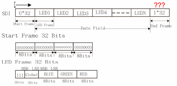
[Jelmer] opened up his pager and started probing signals to determine what protocol the pager used. Soon he found the RF receiver and decoder IC which implements the POCSAG pager protocol. [Jelmer] began going through the sparse POCSAG documentation and assembled enough information to implement the protocol himself.

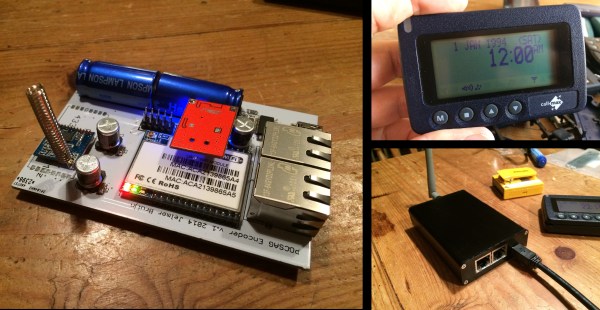
[Jelmer] used a HLK-RM04 WiFi router module for the brains of his build, which talks to an ATMega that controls a SI4432 RF transceiver. The router runs OpenWRT and generates POCSAG control signals that are transmitted by the SI4432 IC. [Jelmer] successfully used this setup to send control signals to several pagers he had on hand, and plans on using the setup to send customizable alerts in the future. [Jelmer] does note that operating this device may be illegal in many countries, so as always, check local frequency allocations and laws before tackling this project. Check out the video after the break where a pager is initialized by [Jelmer]’s transmitter.

Continue reading “Bringing A Legacy Pager Network Back To Life”

FPGA Ambilight Clone Packs A Ton Of Features

[Stephen] designed a standalone Ambilight clone built around an FPGA and recently added many new features to make his design even better. His original design was based around a Spartan 3-E FPGA, but his new design uses the Papilio One board with a Spartan-6 LX9 FPGA. This gives him dedicated DSP hardware and more RAM, allowing him to add more processing-intensive features.

[Steven]’s new board can drive up to 4096 LEDs total, and each LED is colored from one of 256 segmented screen areas. The output of the LEDs is smoothed over a configurable time period which makes the result a bit more pleasant. [Steven] also added color correction matrices and gamma correction tables to make up for differences in LED coloration and so the output can be fine-tuned to the color of the wall behind the TV.

Finally, [Steven] added multiple configurations which can be stored in Flash memory. The FPGA can detect letterboxes and pillarboxes in the video stream and change to a corresponding configuration automatically, so settings rarely need to be manually adjusted. He also added an extensive serial interface to configure all of the parameters and configurations in Flash. Be sure to check out the video after the break to see his setup in action.

Continue reading “FPGA Ambilight Clone Packs A Ton Of Features”

Reverse-Engineering A Game Boy Clone’s Boot ROM

[nitro2k01] got his hands on a Game Fighter, a clone of the original Game Boy. While there’s a ton of information about the boot ROM and operation of the original Game Boy, not much is known about these clones. [nitro2k01] wanted to learn more, so he used a clock-glitching technique to dump the device’s ROM and made some interesting discoveries about its copyright protection and boot process along the way.

Reading the contents of the Game Boy ROM is a bit challenging. The ROM is readable while booting, but afterwards the address space of the ROM is remapped for interrupt vectors and other uses. There are a couple of methods to get around this, but the simplest method involves glitching the crystal by grounding one of its leads. This causes the CPU to jump to random locations in memory. Eventually the CPU will jump to a location where the boot ROM is accessible (if you’re lucky!).

Although [nitro2k01]’s clone can run the same games as the Game Boy, it has a different boot ROM and also has some significant hardware differences. [nitro2k01] managed to use a modified version of the crystal-grounding technique to glitch his clock and dump the clone’s boot ROM. He found that the clone uses an unusual variation on the Game Boy’s copyright-checking technique, along with some other oddities. [nitro2k01] also posted a disassembly of the boot ROM, which he explains in detail.

Thanks for the tip, [Ove].

Digging Into The APA102 Serial LED Protocol

[Tim] got his hands on some APA102 RGB LEDs, which are similar in function to the common WS2812 addressable LEDs seen in many projects we’ve featured. The advantage of APA102 LEDs is that they don’t have the strict timing requirements of the WS2812. These LEDs are controlled with a SPI bus that can be clocked at any arbitrary rate, making them easy to use with pretty much any microcontroller or embedded system.

After working with the LEDs, [Tim] discovered that the LEDs function a bit differently than the datasheet led him to believe. [Tim] controlled a strand of APA102 LEDs with an ATtiny85 and connected a logic analyzer between some of the LEDs. He discovered that the clock signal of the SPI interface isn’t just passed through each LED, it actually looks like it’s inverted on the output. After some investigation, [Tim] found that the clock signal is delayed by a half period (which looks like an inversion) before it’s passed to the next LED. This gives the next LED in the strand enough time for data on the data line to become valid before latching it in.

Since the clock is delayed, [Tim] discovered that additional bits must be clocked as an “end frame” to generate clock signals which propagate the remaining data to the end of the strand. Although the datasheet specifies a 32-bit end frame, this only works for strings of up to 64 LEDs. More bits must be added to the end frame for longer strands, which the datasheet doesn’t even mention. Check out [Tim]’s post for more information, where he walks you through his logic analysis of the APA102 LEDs.

Overhauling A 3-Zone Reflow Oven

[Ed] owns a 3-zone reflow oven (which he coincidently uses to manufacture reflow oven controllers), but its performance has gotten worse and worse over time. The speed of the conveyer belt became so inconsistent that most boards run through the oven weren’t completely reflowed. [Ed] decided to rip out the guts of the oven and replace it with an Arduino, solving the belt problem and replacing the oven’s user-unfriendly interface

When [Ed] was looking into his belt speed problem, he discovered that the belt motor was controlled by an adjustable linear regulator with no feedback. Although this seems a bit sketchy by itself, the motor also had some mechanical issues and [Ed] ended up replacing it entirely. After realizing that closed-loop speed control would really help make the oven more consistent, [Ed] decided to overhaul all of the electronics in the oven.

[Ed] wanted to make as little custom hardware as possible, so he started out with an Arduino Mega and some MAX31855’s that measure multiple thermocouples in the oven. The Arduino controls the belt speed and runs PID loops which control heating elements in each of the oven’s 3 zones. The Arduino can be programmed with different profiles (stored in EEPROM) which are made up of 3 zone temperatures and a conveyor speed. Don’t have a 3-zone oven of your own to hack? Check out some DIY reflow oven builds we’ve featured before.

An MSP430-based Automatic Fish Feeder

[Dmitri] wanted to buy an automatic feeding setup for his aquarium, but he found that most off-the-shelf feeders are really inaccurate with portion control. [Dmitri]’s fish is sensitive to overfeeding, so an off-the-shelf feeder wouldn’t get the job done. Since [Dmitri] knows a thing or two about electronics, he set out to build his own microcontroller-based automatic feeding machine.

[Dmitri]’s machine is based around a MSP430 that starts feeding at scheduled times and controls how much food is dispensed. The MSP lives on a custom PCB that [Dmitri] designed, which includes a stepper motor driver and input for an endstop sensor. The board is wired to a stepper motor that advances a small wooden board with a series of holes in it. Each hole is filled with a single serving of food. The board slides along a piece of U-channel, and food drops out of each hole into the aquarium when the hole reaches the end of the channel.

The whole build is very well documented, and [Dmitri] explains each block of his schematic in detail. His firmware is also open-source, so you can build your own fish feeder based off of his design. Check out the video after the break to see the feeder in action.

Continue reading “An MSP430-based Automatic Fish Feeder”

Chaos Theory In Practice: Chua’s Circuit

Chua’s circuit is the simplest electronic circuit that produces chaos—the output of this circuit never repeats the same sequence, and is a truly random signal. If you need a good source of randomness, Chua’s circuit is easy to make and is built around standard components that you might have lying around. [Valentine] wrote a comprehensive guide which walks you through the process of building your own source of chaos.

The chaos of Chua’s circuit is derived from several elements, most importantly a nonlinear negative resistor. Unfortunately for us, this type of resistor doesn’t exist in a discrete form, so we have to model it with several other components. This resistor, also known as Chua’s diode, can be created with an op-amp configured as a negative impedance converter and a couple pairs of diodes and resistors. Other variations such, as the schematic above,22`01 model Chua’s diode using only op-amps and resistors.

The rest of the circuit is quite simple: only two capacitors, an inductor, and a resistor are needed. [Valentine] does note that the circuit is quite sensitive, so you might encounter issues when building it on a breadboard. The circuit is very sensitive to vibration (especially on a breadboard), and good solder connections are essential to a reliable circuit. Be sure to check out the Wikipedia article on Chua’s circuit for a brief overview of the circuit’s functionality and a rabbit trail of information on chaos theory.