Painting With Light: The Homemade Pixelstick

Light painting has long graced the portfolios of long-exposure photographers, but high resolution isn’t usually possible when you’re light painting with human subjects.

This weekend project from [Timmo] uses an ESP8266-based microcontroller and an addressable WS2812-based LED strip to paint words or custom images in thin air. It’s actually based on the Pixelstick, a tool used by professional photographers for setting up animations and photorealism shots. The equipment needed for setting up the light painting sticks runs in the order of hundreds, not to mention the professional camera and lenses needed. Nevertheless, it’s a huge step up from waving around a flashlight with your friends.

The LED Lightpainter takes the Pixelstick a few notches lower for amateur photographers and hobbyists. It directly supports 24-bit BMP, with no conversion needed. Images are stored internally in Flash memory and are uploaded through a web interface. The settings for the number of LEDs, time for the image row, and STA/AP-mode for wireless connections are also set by the web interface. The project uses the Adafruit NeoPixel, ArduinoJson, and Bodmer’s TFT_HX8357 libraries for implementing the BMP drawing code, which also allows for an image preview prior to uploading the code to the microcontroller. Images are drawn from the bottom row to the top, so images have to be transformed before updating to the LED painter.

Some future improvements planned for the project include TFT/OLED support, rainbow or color gradient patterns in the LEDs, and accelerometer or gyroscope support for supporting animation.

There aren’t currently too many galleries of DIY LED-enabled light paintings, but we’d love to see some custom modded light painting approaches in the future.

This isn’t the first LED light stick we’ve seen, if you’re interested in such things.

The Smallest Homebrewed TTL CPU In The World

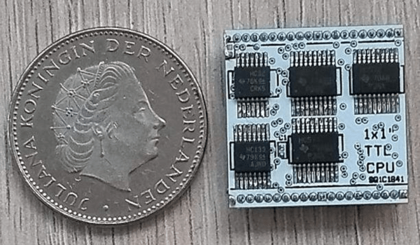
This may very well be the smallest homemade TTL CPU we’ve ever seen. Measuring at one square inch, this tiny chip boasts 40 connections, an 8-bit databus, a 16-bit address bus, a 64 kB memory space, reset and clock inputs, and 5 V power lines.

TTL (transistor transistor logic) logic chips are pretty outdated today, but they do have all of the basics necessary for building a computer – logic gates, counters, buffers, and registers. The transistors perform both the logic and amplifying, as compared to resistor-transistor logic (RTL) and diode-transistor logic (DTL). In the 60s, when the technology was still fairly new, TTL ICs were commonly used in computers and industrial controls. Even after the advent of VLSI, TTL ICs were still being used for interfacing more densely integrated chips. Even so, most TTL chips tend to be on the bulkier side, which is what makes [roelh]’s project so unique. The entire PCB is hardly any larger than a coin.

On top of the hardware specs, [roelh] also implemented several useful software features: zero page addressing, load/store/compare instructions, stacks, conditioning branching, subroutine calls, and memory-mapped I/O. The registers are also in RAM, which has been implemented in microprocessors in the past (see TMS9900) for speed considerations, but in this case was implemented for size constraints.

An ALU was also left out of the design in order to constrain its size, leaving only 8 ICs on either side of the 2-layer PCB.

Microprograms are stored in Flash memory and can be programmed with a Raspberry Pi. by saving the Assembly code to a memory card and downloading the assembled binary code. Once the Raspberry Pi is connected to the development board, you can burn the binary code onto the Flash memory of the board using a Python script. An online Javascript editor also exists for assembling the Assembly code for the chip and simulating the CPU.

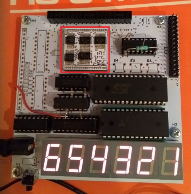
There is currently a development board made for the CPU, which includes six seven-segment displays and an I/O connector for running a digital clock and other applications. [roelh] has since built a retro TTL computer around the chip, which reintroduces the ALU and includes address registers, 256 KB of RAM, VGA video, PS/2 keyboard port, a sound system, and I/O pins. It’s a really exciting project that’s seriously pushing the constraints of retro computing.

How To Build The Strongest Arches

When it comes to architectural features, there are probably not many as quintessentially memorable as arches. From the simplicity of the curved structure to the seemingly impossible task of a supposedly collapsable shape supporting so much weight in mid-air, they’ve naturally fascinated architects for generations.

For civil engineers, learning to calculate the forces acting on an arch, the material strength and properties, and the weight distribution across several arches may be familiar, but for anyone with only a basic physics and CAD background, it’s easy to take arches for granted. After all, they grace the Roman aqueducts, the Great Wall of China, and are even present in nature at Arches National Park. We see them in cathedrals, mosques, gateways, and even memorialized in the case of the St. Louis Gateway Arch. Even the circular construction of watch towers and wells, as well as our own rib cages, are due to the properties of arches.

But what really goes into constructing a strong arch? Continue reading “How To Build The Strongest Arches”

What Better Than A Hexapod?

What’s more awesome than a normal hexapod robot? What about a MEGA hexapod?

Max the Megapod, a six-legged 3D-printed walking robot, is an open source, Arduino-based, Bluetooth controlled, Scratch programmable creation made possible by [Steven Pendergrast]. The design for Max was based on a previous hexapod project, Vorpal the Hexapod, which has since been built at hundreds of schools worldwide.

Max clocks in at two feet in diameter, expanding to three when sprawled out on the ground. In addition, the hexapod is able to dance, walk, and run as fast as the smaller version, covering ground at twice the speed due to its size.

The scaling for the project – about 200% from the original hexapod – required some creativity, as the goal was for the components to be printed on a modest-sized printer with an 8 inch cube bed. In addition, since Max weighs 9 pounds on average, real bearings (608 Skate bearings) needed to be used for the servo mounts.

The electrical system had to be changed to account for the larger currents drawn by the larger servos (MG958s). and the power distribution harness needed to be redesigned. The current harness take about two hours to build for the larger hexapod, compared to 15 minutes for the original design.

The results are both hilarious and adorable, especially given the endless modifications made to give Max a unique flair. Perhaps a GIGApod could be coming up next?

Continue reading “What Better Than A Hexapod?”

A (Mostly) 3D Printed Servo/Gear Reduction

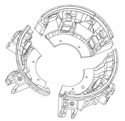
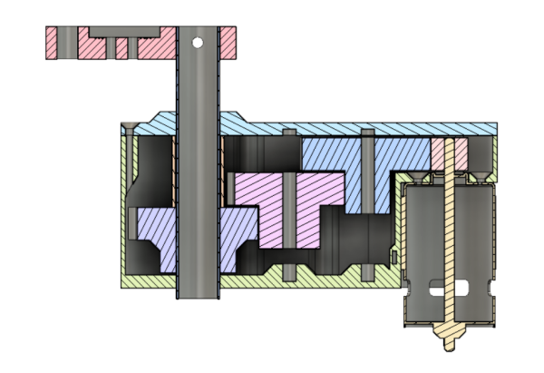
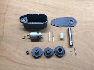
This servo/gear reduction was assembled with almost all 3D-printed parts. Apart from a brushed 36 V DC-motor, a stainless steel shaft, and screws for holding the servo together, the only other non-printed part is the BTS7960B motor driver.

Some interesting stats about the plastic servo – its stall torque is about 55 kg/cm, reaching a peak current draw of 18 A when using a 6s LiPo battery outputting 22-24 V. The shaft rotates using two 20 mm holes and lubrication. (Ball bearings were originally in the design, but they didn’t arrive on time for the assembly.)

The holes of the gears are 6.2 mm in diameter in order to fit around the shaft, although some care is taken to sand or fill the opening depending on the quality of the 3D print.

This isn’t [Brian Brocken]’s only attempt at 3D-printing gears. He’s also built several crawling robots, a turntable, and a wind up car made entirely from acrylic. The .stl files for the project are all available online for anyone looking to make their own 3D-printed servo gears.

Continue reading “A (Mostly) 3D Printed Servo/Gear Reduction”

The World’s Smallest Vacuum In An Altoids Tin

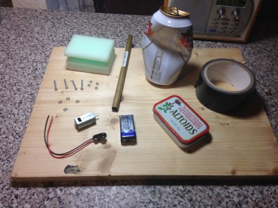
There’s been a lot of Altoids tin hacks over the years, but a vacuum cleaner in a tin is something new. In [Toby Bateson]’s first project on Hackaday, he used simple household items to create a functioning vacuum cleaner to use for sucking crumbs out of your keyboard or paper punch holes off your desk.

The vacuum features a retractable suction tube, a low-profile switch, and a bagless waste collection system (the waste is stored and discarded out from the tin itself). A brushed motor and impeller provide the airflow. A scrap of a beer can mounted on the shaft is used for an impeller blade, and two bolts with a thin metal sheet between them are made into a switch (the instructions recommend you finish your drink before using the scrap metal). A sponge is used for filtering the dirt from the motor while a hole is cut out of the top of the tin to provide airflow.

[Bateson] is looking to put his name in the world record book for the world’s smallest vacuum tube, as he recently created an even smaller vacuum in a 1cc tube.

“Oh dear, I’ve spilled something on my desk, whatever am I going to do? Luckily, I have my vacuum cleaner in an Altoids tin…”

Continue reading “The World’s Smallest Vacuum In An Altoids Tin”

Dealing With Missing Pin Allocations

Blindsided by missing pin allocations? Perhaps you’re working on a piece of hardware and you notice that the documentation is entirely wrong. How can you get your device to work?

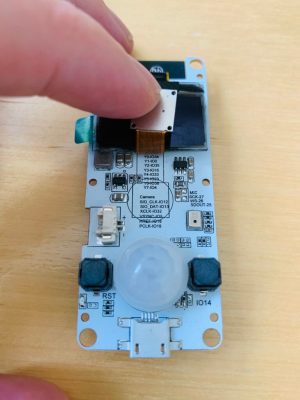
[Dani Eichhorn]’s troubles began when running an IoT workshop using a camera module. Prior to the work, no one had through to check if all of the camera modules ordered for the participants were the same. As it turns out, the TTGO T-CAM module had a number of revisions, with some even receiving a temperature/pressure sensor fixed on top of the normal board.

While the boards may have looked the same, their pin allocations were completely different.Changing the pin numbers wouldn’t have been difficult if they were simply numbered differently, but because the configurations were different, errors started to abound: Could not initialize the camera

As it turns out, even the LillyGo engineers – the manufacturers of the board – may have gotten a bit lost while working on the pin allocations, as [Eichhorn] was able to find some of the pins printed right onto the PCB, hidden behind the camera component.

To find information not printed on the board, a little more digging was required. To find the addresses of the devices connected to the I2C bus, running a program to find peripherals listening on the bus did the trick. This was able to print out the addresses of the SSD1306 OLED display driver and the microphone for the board at hand.

To find the pins of peripherals not printed on the PCB or hidden on the silkscreen, a GPIO scanner did the trick. This in particular worked for finding the PIR (passive infrared) motion sensor.

We picked up a few tips and tricks from this endeavor, but also learned that reverse-engineering anything is hard, and that there isn’t any one method for finding pin allocations when the documentation’s missing.