Make Your Own Plasma Cutter

Of all the tools that exist, there aren’t many more futuristic than the plasma cutter, if a modern Star Wars cosplay if your idea of futuristic. That being said, plasma cutters are a powerful tool capable of making neat cuts through practically any material, and there are certainly worst ways to play with high voltage.

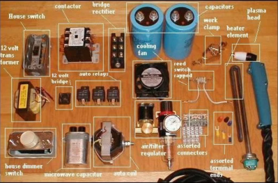
Lucky enough, [Plasanator] posted their tutorial for how to make a plasma cutter, showing the steps through which they gathered parts from “old microwaves, stoves, water heaters, air conditioners, car parts, and more” in the hopes of creating a low-budget plasma cutter better than any on YouTube or from a commercial vendor.
The plasma cutter does end up working up quite an arc, with the strength to slice through quarter-inch steel “like a hot knife through butter”.

Its parts list and schematic divide the systems into power control, high current DC, low voltage DC, and high voltage arc start:

  • The power control contains the step down transformer and contactor (allows the DC components to come on line)
  • The high current DC contains the bridge rectifier, large capacitors, and reed switch (used as a current sensor to allow the high voltage arc to fire right when the current starts to travel to the head, shutting down the high voltage arc system when it’s no longer necessary)
  • The low voltage DC contains the power switch, auto relays, 12V transformer, 120V terminal blocks, and a terminal strip
  • The high voltage arc start contains the microwave capacitor and a car ignition coil

At the cutting end, 13A is used to cut through quarter-inch steel. Considering the considerably high voltage cutter this is, a 20 A line breaker is needed for safety.

Once the project is in a more refined state, [Plasanator] plans on hiding components like the massive capacitors and transformer behind a metal or plastic enclosure, rather than have them exposed. This is mainly for safety reasons, although having the parts exposed is evocative of a steampunk aesthetic.

In several past designs, stove coils were used as current resistors and a Chevy control module as the high voltage arc start. The schematic may have become more refined with each build, but [Plasanator]’s desire to use whatever components were available certainly has not disappeared.

Continue reading “Make Your Own Plasma Cutter”

How To Make A Living With Embedded Systems

One of the biggest dreams anyone has is to make a living doing what they love. For all hackers, makers, and DIYers with a passion for embedded systems, it may make sense initially to pursue embedded systems design as a possible career, but without so much information on the types of qualifications or steps needed to actually secure a job offer, it may seem daunting to try and break into the field.

YouTuber [iAyan Pahwa] currently works as an embedded software engineer, having been in the field for two years, with prior experience as a hobbyist working with microcontrollers, motors, and programming in the embedded domain. In this video, embedded below, he provides his take on what you need to know to get yourself that first job.

Continue reading “How To Make A Living With Embedded Systems”

Sending An ESP32 Into Space

Just two weeks ago, the crew from the International Space Station released a photo of their nine crew members – an odd number considering that the facility only has space to house six astronauts at a time. In fact, the crew had just gathered for a celebratory dinner before three of the astronauts were to return home. The new astronauts joining including Hazza Al Mansouri, the first astronaut from the United Arab Emirates (who has since returned from his mission), as well as astronaut Jessica Meir and cosmonaut Oleg Skripochka.

Amidst the excitement over the upcoming 10 (!) spacewalks in the next three months, there’s also been some cool developments in the open source space, with one of the first ESP32s launched into space.

[Nico Maas] from the Microgravity User Support Center (MUSC) at DLR (German Aerospace Center) worked on an experiment launched by MORABA (Mobile Rocket Base) at DLR. The launch site was at the Esrange Space Center in Kiruna, Sweden, with the mission launching on June 13, 2019 at 4:21 am local time.

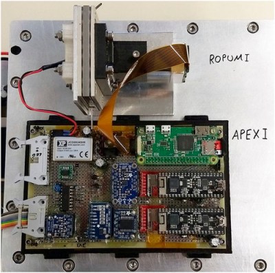
The experiment – APEX (Advanced Processors, Encryption, and Security Experiment) was onboard the ATEK / MAPHEUS-8, mission, rising to an altitude of 240km into space and returning back to earth after six minutes of microgravity.

[via AIP]
The goal of the research was to develop an off-the-shelf computer with a more powerful system for high-speed sensors and image acquisition than the Microchip ATmega328P, the current standard. The flight test measured the speed of the system as well as stress testing its ability to handle compute-intensive tests.

The main board included two ESP32s and a Raspberry Pi Zero W, running resinOS / balenaOS, an operating system designed to run parallel Docker containers and optimized for IoT fleet management.

Prior to the experiment, the standard for on-board computers for use in CubeSats was the ATmega/Arduino-based ARDUSAT. Since it was first made available for use in CubeSats in 2013, the performance has become limited, with improvements needed to perform higher throughput data sampling or operations requiring more computational power.

It’s also cool to note that the system, built using a 3D-printed holder, survived the re-entry (reaching up to 20.6g) with hardly a scratch.

Continue reading “Sending An ESP32 Into Space”

The Cutest Oscilloscope Ever Made

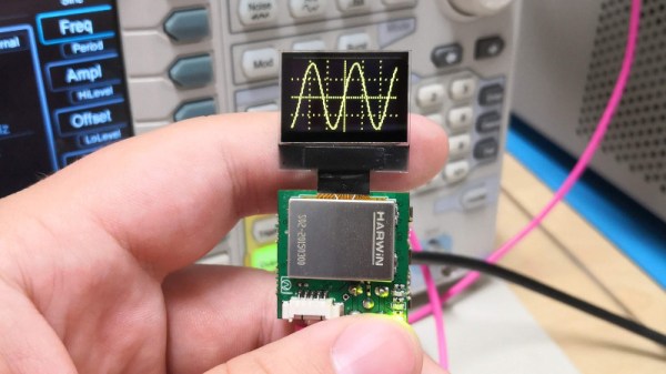
If you thought your handheld digital oscilloscope was the most transportable of your signal analyzing tools, then you’re in for a surprise. This oscilloscope made by [Mark Omo] measures only one square inch, with the majority of the space taken up by the OLED screen.

It folds out into an easier instrument to hold, and admittedly does require external inputs, so it’s not exactly a standalone tool. The oscilloscope runs on a PIC32MZ EF processor, achieving 20Msps and 1MHz of bandwidth. The former interleaves the processor’s internal ADCs in order to achieve its speed.

For the analog front-end the signals first enter a 1M ohm terminator that divide the signals by 10x in order to measure them outside the rails. They then get passed through a pair of diodes connected to the rails, clamping the voltage to prevent damage. The divider centers the incoming AC signal around 1.65V, halfway between AGND and +3.3V. As a further safety feature, a larger 909k Ohm resistor sits between the signals and the diodes in order to prevent a large current from passing through the diode in the event of a large voltage entering the system.

The next component is a variable gain stage, providing either 10x, 5x, or 1x gain corresponding to 1x, 0.5x, and 0.1x system gains. For the subsystem, a TLV3541 op-amp and ADG633 tripe SPDT analog switch are used to provide a power bandwidth around the system response due to driving concerns. Notably, the resistance of the switch is non-negligible, potentially varying with voltage. Luckily, the screen used in the oscilloscope needs 12V, so supplying 12V to the mux results in a lower voltage and thus a flatter response.

The ADC module, PIC32MZ1024EFH064, is a 12-bit successive approximation ADC. One advantage of his particular ADC is that extra bits of resolution only take constant time, so speed and accuracy can be traded off. The conversion starts with a sample and hold sequence, using stored voltage on the capacitor to calculate the voltage.

Several ADCs are used in parallel to sample at the same time, resulting in the interleaving improving the sample rate. Since there are 120 Megabits per second of data coming from the ADC module, the Direct Memory Access (DMA) peripheral on the PIC32MZ allows for the writing of the data directly onto the memory of the microcontroller without involving the processor.

The firmware is currently available on GitHub and the schematics are published on the project page.

Continue reading “The Cutest Oscilloscope Ever Made”

The Next Generation Arduino Nano

While we certainly do love the Arduino Nano for its low-cost and versatility in projects, it’s unarguable that every tools has its gripes. For one maker in particular, there were enough complaints to merit a redesign of the entire board. While Arduino may or may not be interested in incorporating these changes into a redesign of the development board, there is certainly room for a new manufacturer to step in and improve some features.

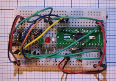
[Kevin Timmerman] takes a look at lower-cost clones of the Nano made in China to highlight a few interesting key differences that make the clones – cheaper but still compatible with legacy systems – more attractive.

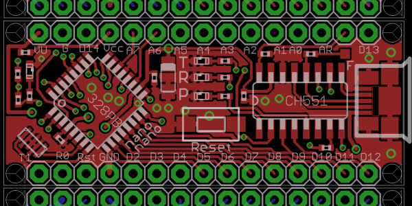
The PCB manufacturing for the Arduino Nano currently places components on both sides of the board, requiring two operations for solder paste, pick-and-place, and reflow. Naturally this increases costs, simply designing a two-layer PCB with components on top lowers the price of manufacturing.

Since the ATmega328PB was released, it has proven to be a better and cheaper MCU for manufacturing than the ATmega328P, the current MCU used by the Arduino Nano and clones. While the newer MCU is not backwards compatible like its predecessor, it has additional UART, GPIO, counters, and other features that allow users to take advantage of new libraries and peripherals.

Rather than featuring the typical voltage regulator used by Arduino boards (used to allow the board to be powered by a voltage source greater than 5V), a switching regulator allows for less energy loss but a higher component cost. A better solution than both of these would be to simply not have a voltage regulator. While this may be controversial, there are sufficient battery power sources for this design to work (4 cells of AA or AAA NiMh batteries or a mobile phone charger).

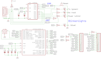
The Arduino Nano uses a bootloader for handling programming the MCU, which requires the USB to serial bridge to be disconnected from anything that could interfere with the programming. Thus, programs using the COM port on the computer must release the port, including the serial monitor. Rather than using the bootloader, ICSP (in-circuit serial programming) and DebugWire are possible alternatives that connect the ICSP pins to the CH551 development board or programming via the reset pin.

There are a number of other spec and firmware improvements suggested in the writeup, as well as comparison between the Arduino Nano, Arduino Every, and Chinese clones. It’s definitely worth a look!

This Sentence‌‌‌‌‍‌ Isn’‌‌‌‌‍‌‬t Just ‌‌‌‌‌‬‌‌a‌‌‌‌‍‬‬‍ Sentence‌‌‌‌‍‌‌‌‌‌‌‬‌‌‌‌‌‌‍‬‬‍‌‌‌‌‍‍‌‌‌‌‌‌

Some sentences have more than meets the eye, and we’re not talking about interpretive nonsense. Rather, some sentences may contain up to four paragraphs’ worth of hidden text, invisible to readers.

Thanks to Zero Width Obfuscation, it is possible to use Zero Width Characters – Unicode characters that are invisible even when you try to highlight them. They’re typically used for abstract foreign languages that require separators that don’t take up an entire space. In this case, they’re used to obfuscate and de-obfuscate hidden messages sent through text.

[inzerosight] published a browser extension that identifies, de-obfuscates, and obfuscates these messages for you on the web. It does this by querying each page for the Unicode of the Zero Width Characters (U+FEFF, U+200C, U+200D, U+200E, U+2060, U+180E) and highlighting where they’ve been spotted. The encoding replaces each Unicode character with a permutation of two of the Zero Width Characters, essentially doing a find and replace across the text message.

I’m just waiting to see how long it takes for Zero Width Obfuscation to become the next Konami Code Easter Egg.

How Random Is Random?

Many languages feature a random number generator library for help with tasks like rolling a die or flipping a coin. Why, you may ask, is this necessary when humans are perfectly capable of randomly coming up with values?

[ex-punctis] was curious about the same quandary and decided to code up an experiment to test the true randomness of human. A script guesses the user’s next input from two choices, keeping a tally in the JavaScript backend that holds on to the past five choices. If the script guesses correctly, they take $1 from the user. Otherwise, the user earns $1.05.

The data from gathered from running the script with 200 pseudo-random inputs 100,000 times resulted in a distribution of correct guess approximately normal (µ=50% and σ=3.5%). The probability of the script correctly guessing the user’s input is >57% from calculating µ+2σ. The result? Humans aren’t so good at being random after all.

It’s almost intuitive why this happens. Finger presses tend to repeat certain patterns. The script already has a database of all possible combinations of five presses, with a counter for each combination. Every time a key is pressed, the latest five presses is updated and the counter increases for whichever combination of five presses this falls under. Based on this data, the script is able to make a prediction about the user’s next press.

In a follow-up statistic analysis, [ex-punctis] notes that with more key presses, the accuracy of the script tended to increase, with the exception of 1000+ key presses. The latter was thought to be due to the use of a psuedo random number generator to achieve such high levels of engagement with the script.

Some additional tests were done to see if holding shorter or longer sequences in memory would account for more accurate predictions. While shorter sequences should theoretically work, the risk of players keeping a tally of their own presses made it more likely for the longer sequences to reduce bias.

There’s a lot of literature on behavioral models and framing effects for similar games if you’re interested in implementing your own experiments and tricking your friends into giving you some cash.