Building IoT Devices The Easy Way

Do you have a Raspberry Pi? What is it being used for right now? If you’re like the majority of people who replied to [Michael Hall’s] poll on Twitter, it’s likely yours is sitting on a shelf doing nothing too. So why not just turn it into an IoT device for your home?

[Michael] wrote an easy-to-follow guide focusing on getting the EdgeX Foundry IoT platform running on the Raspberry Pi. It is designed to be a unified multi-platform base for IoT devices hosted by the Linux Foundation, making it easy to control and integrate them into other systems. The framework for this consists of two parts, a Device Service running on your Pi, and the rest of the services running on a desktop or laptop where you’ll be monitoring it.

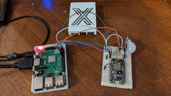
His guide goes into detail on how to get both parts working on your computer and your Pi using Docker for ease of installation. As for the IoT device, he uses the built-in PIR sensor example to show how to configure it without having to write any programming. You can then monitor the device’s sensors, which you can just connect straight to the Pi’s GPIO pins, from your desktop. Since the EdgeX software is designed to run on any flavor of Linux, this should make it easy to repurpose any forgotten single-board computer into the beginnings of a home automation system.

However, if you are confident in your programming skills, you’re probably looking for something slimmer such as the ESP8266 family of microcontrollers to do your bidding. Why not try an energy monitor or a smoke detector project with them?

Fail Of The Week: How Not To Re-Reflow

There’s no question that surface-mount technology has been a game-changer for PCB design. It means easier automated component placement and soldering, and it’s a big reason why electronics have gotten so cheap. It’s not without problems, though, particularly when you have no choice but to include through-hole components on your SMT boards.

[James Clough] ran into this problem recently, and he tried to solve it by reflowing through-hole connectors onto assembled SMT boards. The boards are part of his electronic lead screw project, an accessory for lathes that makes threading operations easier and more flexible. We covered the proof-of-concept for the project; he’s come a long way since then and is almost ready to start offering the ELS for sale. The PCBs were partially assembled by the board vendor, leaving off a couple of through-hole connectors and the power jack. [James]’ thought was to run the boards back through his reflow oven to add the connectors, so he tried a few experiments first on the non-reflow rated connectors. The Phoenix-style connectors discolored and changed dimensionally after a trip through the oven, and the plastic on the pin headers loosened its grip on the pins. The female header socket and the power jack fared better, so he tried reflowing them, but it didn’t work out too well, at least for the headers. He blames poor heat conduction due to the lack of contact between the board and the reflow oven plate, and we agree; perhaps an aluminum block milled to fit snugly between the header sockets would help.

Hats off to [James] for trying to save his future customers a few steps on assembly, but it’s pretty clear there are no good shortcuts here. And we highly recommend the electronic leadscrew playlist to anyone interested in the convergence of machine tools and electronics.

Continue reading “Fail Of The Week: How Not To Re-Reflow”

The Cutest Oscilloscope Ever Made

If you thought your handheld digital oscilloscope was the most transportable of your signal analyzing tools, then you’re in for a surprise. This oscilloscope made by [Mark Omo] measures only one square inch, with the majority of the space taken up by the OLED screen.

It folds out into an easier instrument to hold, and admittedly does require external inputs, so it’s not exactly a standalone tool. The oscilloscope runs on a PIC32MZ EF processor, achieving 20Msps and 1MHz of bandwidth. The former interleaves the processor’s internal ADCs in order to achieve its speed.

For the analog front-end the signals first enter a 1M ohm terminator that divide the signals by 10x in order to measure them outside the rails. They then get passed through a pair of diodes connected to the rails, clamping the voltage to prevent damage. The divider centers the incoming AC signal around 1.65V, halfway between AGND and +3.3V. As a further safety feature, a larger 909k Ohm resistor sits between the signals and the diodes in order to prevent a large current from passing through the diode in the event of a large voltage entering the system.

The next component is a variable gain stage, providing either 10x, 5x, or 1x gain corresponding to 1x, 0.5x, and 0.1x system gains. For the subsystem, a TLV3541 op-amp and ADG633 tripe SPDT analog switch are used to provide a power bandwidth around the system response due to driving concerns. Notably, the resistance of the switch is non-negligible, potentially varying with voltage. Luckily, the screen used in the oscilloscope needs 12V, so supplying 12V to the mux results in a lower voltage and thus a flatter response.

The ADC module, PIC32MZ1024EFH064, is a 12-bit successive approximation ADC. One advantage of his particular ADC is that extra bits of resolution only take constant time, so speed and accuracy can be traded off. The conversion starts with a sample and hold sequence, using stored voltage on the capacitor to calculate the voltage.

Several ADCs are used in parallel to sample at the same time, resulting in the interleaving improving the sample rate. Since there are 120 Megabits per second of data coming from the ADC module, the Direct Memory Access (DMA) peripheral on the PIC32MZ allows for the writing of the data directly onto the memory of the microcontroller without involving the processor.

The firmware is currently available on GitHub and the schematics are published on the project page.

Continue reading “The Cutest Oscilloscope Ever Made”

Minature Table Saw Gets The Teeny Jobs Done

Table saws are highly useful tools, but tend to take up a lot of space. They’re usually designed to handle the bigger jobs in a workshop. It doesn’t have to be that way, however, as [KJDOT] demonstrates with a miniature table saw.

It’s a saw that relies on a simple build. The frame is made of plywood, and can be built with just a drill and a hand saw. A brushed motor is used to run the saw, using an off-the-shelf PWM controller and a 24V power supply. A handful of bearings and standard brackets are then used to put it all together, and there’s even a handy adjustable fence to boot. With a 60mm blade fitted, the saw is ready to go.

It’s a build that would be great for anyone regularly working with wood or plastics on the smaller scale. If you like building dollhouses, this could be the tool for you. You might also find the table nibbler to be an enticing proposition. Video after the break.

Continue reading “Minature Table Saw Gets The Teeny Jobs Done”

The Next Generation Arduino Nano

While we certainly do love the Arduino Nano for its low-cost and versatility in projects, it’s unarguable that every tools has its gripes. For one maker in particular, there were enough complaints to merit a redesign of the entire board. While Arduino may or may not be interested in incorporating these changes into a redesign of the development board, there is certainly room for a new manufacturer to step in and improve some features.

[Kevin Timmerman] takes a look at lower-cost clones of the Nano made in China to highlight a few interesting key differences that make the clones – cheaper but still compatible with legacy systems – more attractive.

The PCB manufacturing for the Arduino Nano currently places components on both sides of the board, requiring two operations for solder paste, pick-and-place, and reflow. Naturally this increases costs, simply designing a two-layer PCB with components on top lowers the price of manufacturing.

Since the ATmega328PB was released, it has proven to be a better and cheaper MCU for manufacturing than the ATmega328P, the current MCU used by the Arduino Nano and clones. While the newer MCU is not backwards compatible like its predecessor, it has additional UART, GPIO, counters, and other features that allow users to take advantage of new libraries and peripherals.

Rather than featuring the typical voltage regulator used by Arduino boards (used to allow the board to be powered by a voltage source greater than 5V), a switching regulator allows for less energy loss but a higher component cost. A better solution than both of these would be to simply not have a voltage regulator. While this may be controversial, there are sufficient battery power sources for this design to work (4 cells of AA or AAA NiMh batteries or a mobile phone charger).

The Arduino Nano uses a bootloader for handling programming the MCU, which requires the USB to serial bridge to be disconnected from anything that could interfere with the programming. Thus, programs using the COM port on the computer must release the port, including the serial monitor. Rather than using the bootloader, ICSP (in-circuit serial programming) and DebugWire are possible alternatives that connect the ICSP pins to the CH551 development board or programming via the reset pin.

There are a number of other spec and firmware improvements suggested in the writeup, as well as comparison between the Arduino Nano, Arduino Every, and Chinese clones. It’s definitely worth a look!

Tools, You Can’t Take Them With You

When I die I hope be buried in the English rural churchyard that has been my responsibility as churchwarden, after a funeral service that has been a celebration of my life. I am neither an Egyptian pharaoh nor a Viking queen though, so my grave will not contain all my tools and equipment to serve me in the afterlife. Instead aside from my mortal remains it will contain only a suitably biodegradable coffin, and my headstone will be a modest one bearing perhaps a technical puzzle to entertain visitors to the churchyard.

My workshop, my bench, and my tools will be the responsibility of my nearest and dearest, and I hope I will have suitably equipped them for the task of their dispersal. But for anyone who has a sizeable collection of gear, have you thought of what would happen if someone else had to clean it all out? What is profession for some and hobby for others, we deal in specialization that might as well be tools of arcane magic to the uninitiated.

Continue reading “Tools, You Can’t Take Them With You”

DIY Tiny Dovetail Cube Needs DIY Dovetail Cutter

Dovetail cutter, made from a 5 mm drill rod.

There’s a trinket called a dovetail cube, and [mitxela] thought it would make a fine birthday present. As you can see from the image, he was successful in creating a tiny version out of aluminum and brass. That’s not to say there weren’t challenges in the process, and doing it [mitxela] style means:

  • Make it tiny! 15 mm sides ought to do it.
  • Don’t have a tiny dovetail bit on hand, so make that as well.
  • Of course, do it all without CNC in free-machining style.
  • Whoops the brass stock is smaller than expected, so find a clever solution.
  • That birthday? It’s tomorrow, by the way.

The project was a success, and a few small learning experiences presented themselves. One is that the shape of a dovetail plays tricks on the human eye. Geometrically speaking, the two halves are even but it seems as though one side is slightly larger than the other. [mitxela] says that if he were to do it again, he’d make the aluminum side slightly larger to compensate for this visual effect. Also, deburring with a knife edge on such a small piece flattened the edges ever so slightly, causing the fit to appear less precise than it actually is.

Still, it was a success and a learning experience. Need more evidence that [mitxela] thrives on challenge? Take a look at his incredible vector game console project.