Sanity Check Your Engines With This Dynamometer

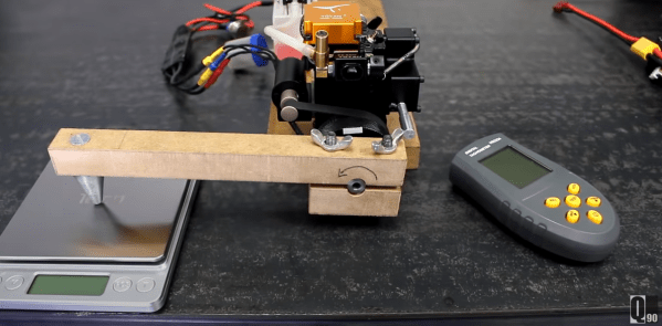
As you get ready to pop the hood of your RC car to drop in a motor upgrade, have you ever wondered how much torque you’re getting from these small devices? Sure, we might just look up the motor specs, but why trust the manufacturer with such matters that you could otherwise measure yourself? [JohnnyQ90] did just that, putting together an at home-rig built almost from a stockpile of off-the-shelf parts.

To dig into the details, [JohnnyQ90] has built himself a Prony Brake Dynamometer. These devices are setup with the motor shaft loosely attached to a lever arm that can push down on a force-measuring device like a scale. With our lever attached, we then power up our motor. By gradually increasing the “snugness” of the motor shaft, we introduce sliding friction that “fights” the motor, and the result is that, at equilibrium, the measured torque is the maximum amount possible for the given speed. Keep turning up that friction and we can stall the motor completely, giving us a measurement of our motor’s stall torque.

Arming yourself with a build like this one can give us a way to check the manufacturer’s ratings against our own, or even get ratings for those “mystery motors” that we pulled out the dumpster. And [JohnnyQ90’s] build is a great reminder on how we can leverage a bit of physics and and a handful of home goods to get some meaningful data.

But it turns out that Prony Brake Dynamometers aren’t the only way of measuring motor torque. For a disc-brake inspired, have a look at this final project. And if you’re looking to go bigger, put two motors head-to-head to with [Jeremy Felding’s] larger scale build.


Continue reading “Sanity Check Your Engines With This Dynamometer”

Removable Extruder Pulls Out The Stops On Features

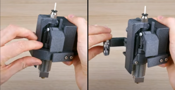
For all of us fascinated with 3D printing, it’s easy to forget that 3D printer jams are an extra dimension of frustration to handle. Not to mention that our systems don’t really lend themselves well to being easily disassembled for experiments. For anyone longing for a simpler tune-up experience, you’re in luck. [MihaiDesigns] is dawning on what looks to be a cleanly designed solution to nozzle-changing, servicing, and experimenting.

The video is only 39 seconds, but this design is packed with clever editions that come together with a satisfying click. First, the active part of the extruder is detachable, popping in-and-out with a simple lever mechanism that applies preload. For consistent attachment, it’s located with a kinematic coupling on the side with a magnet that helps align it. What’s neat about this design is that it cuts down on the hassle of wire harnesses; tools are set to share the same harness via an array of spring-loaded pogo pins. Finally, a quick-change extruder might be neat on its own, but [MihaiDesigns] is teasing us with an automatic tool change feature with a handy lever arm.

This is a story told over multiple sub-60-second videos, so be sure to check out their other recent videos for more context. And for the 3D printing enthusiasts who dig a bit further into [MihaiDesigns’] video log, you’ll be pleased to find more magnetic extruder inventions that you can build yourself.

The world of tool-changing 3D printers is simply brimming with excitement these days. If you’re curious to see other machines with kinematic couplings, have a peek at E3D’s toolchanger designs, Jubilee, and [Amy’s] Doot Changer.

Continue reading “Removable Extruder Pulls Out The Stops On Features”

Cable Mechanism Maths: Designing Against The Capstan Equation

I fell in love with cable driven mechanisms a few years ago and put together some of my first mechanical tentacles to celebrate. But only after playing with them did I start to understand the principles that made them work. Today I want to share one of the most important equations to keep in mind when designing any device that involves cables, the capstan equation. Let some caffeine kick in and stick with me over the next few minutes to get a sense of how it works, how it affects the overall friction in your system, and how you can put it to work for you in special cases.

A Quick Refresher: Push-Pull Cable Driven Mechanisms

But first: just what exactly are cable driven mechanisms? It turns out that this term refers to a huge class of mechanisms, so we’ll limit our scope just to push-pull cable actuation systems.

These are devices where cables are used as actuators. By sending these cables through a flexible conduit, they serve a similar function to the tendons in our body that actuate our fingers. When designing these, we generally assume that the cables are both flexible and do not stretch when put in tension. Continue reading “Cable Mechanism Maths: Designing Against The Capstan Equation”

Control Theory Spellcasting Banishes The 3D Printing Ghosts

It seems as though we still can’t hit the ceiling on better control schemes for 3D Printers. Input Shaping is the latest technique to land on our radar, a form of resonance compensation that all but eliminates the ghosting (aka: vertical ringing) artifacts we see on the walls of printed parts. While the technique has been around for decades, only recently did [Dmitry Butyugin] both apply it to 3D printer control and merge their hard work into the open source firmware package Klipper. Once tuned, the results are simply astonishing–especially since this scheme can augment the print quality of even the most budget printer.

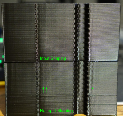
A Split A/B Test with and without Klipper’s Input Shaping feature courtesy of [@LukesLaboratory]
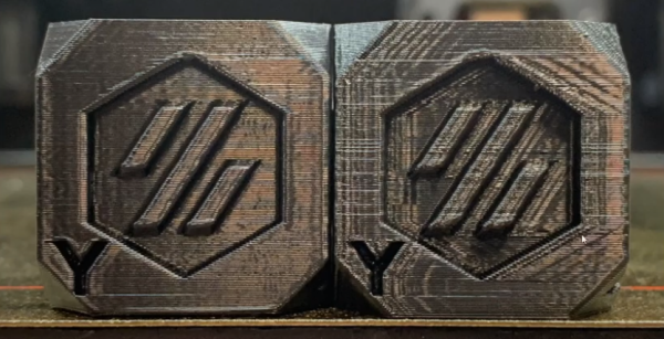
Assuming your 3D printer isn’t infinitely stiff, when your nozzle moves from point to point or changes direction, it vibrates in response to having its speed altered. The result is that the nozzle wobbles along the ideal path it’s trying to track. The result is ghosting, an aesthetic blemish that looks like vertical waves on the sides of your printed part.

Input Shaping is a feed-forward controls technique for cancelling the mechanical vibrations that create ghosting. The idea is that, if we wanted to move the machine from point to point, we send it two impulses. The first impulse kicks the machine into moving and the second impulse follows up at a precise time to cancel the vibrations we would see when the machine comes to a stop. Albeit, moving any machine by sending it two impulses is pretty crude, so we take these impulses, adjust their amplitudes so that they sum to 1, and convolve them with a control input signal that we’d actually like to send it. The result is that the resonance cancellation part of the signal seamlessly “mixes” into the control input signal, and the machine moves from point to point with significantly less vibration at the end of the travel move. For more info on the maths behind this process, have a look at the first four pages of this paper from [Singh and Singhose].

The only hiccup is that you need to do some up-front system characterization of your 3D Printer running Klipper before you can take advantage of this technique. Thankfully the Klipper update comes with a set of step-by-step instructions for characterizing your machine up-front. After a couple test prints to measure the periodicity of your ringing, you can simply apply your measurement results to your config file, and you’re set.

Input Shaping is a prime example of “just wrap a computer around it!“–fixing hardware by characterizing and cancelling unwanted behaviors with software. If you’re hungry for more clever, characterized hardware control schemes, look no further than this Anti-Cogging algorithm for BLDC Motors. And for a video walkthrough of the Klipper implementation, have a look at [eddietheengineer]’s breakdown after the break.

Does your 3D Printer run Klipper? We’d love to see some of your Input Shaping results in the comments.

Continue reading “Control Theory Spellcasting Banishes The 3D Printing Ghosts”

A Case For Project Part Numbers

Even when we share the design files for open source hardware, the step between digital files and a real-world mechatronics widget is still a big one. That’s why I set off on a personal vendetta to find ways to make that transfer step easier for newcomers to an open source mechantronics project.

Today, I want to spill the beans on one of these finds: part numbers, and showcase how they can help you share your project in a way that helps other reproduce it. Think of part numbers as being like version numbers for software, but on real objects.

I’ll showcase an example of putting part numbers to work on one of my projects, and then I’ll finish off by showing just how part numbers offer some powerful community-building aspects to your project.

A Tale Told with Jubilee

To give this idea some teeth, I put it to work on Jubilee, my open source toolchanging machine. Between October 2019 to November 2020, we’ve slowly grown the number of folks building Jubilees in the world from 1 to more than 50 chatting it up on the Discord server. Continue reading “A Case For Project Part Numbers”

A Featherweight Direct Drive Extruder In A Class Of Its Own

Even a decade later, homebrew 3D printing still doesn’t stop when it comes to mechanical improvements. These last few months have been especially kind to lightweight direct-drive extruders, and [lorinczroby’s] Orbiter Extruder might just set a paradigm for a new kind of direct drive extruder that’s especially lightweight.

Weighing in at a mere 140 grams, this setup features a 7.5:1 gear reduction that’s capable of pushing filament at speeds up to 200 mm/sec. What’s more, the gear reduction style and Nema 14 motor end up giving it an overall package size that’s smaller than any Nema 17 based extruder. And the resulting prints on the project’s Thingiverse page are clean enough to speak for themselves. Finally, the project is released as open source under a Creative Commons Non-Commercial Share-Alike license for all that (license-respecting!) mischief you’d like to add to it.

This little extruder has only been around since March, but it seems to be getting a good amount of love from a few 3D printer communities. The Voron community has recently reimagined it as the Galileo. Meanwhile, folks with E3D Toolchangers have been also experimenting with an independent Orbiter-based tool head. And the Annex-Engineering crew has just finished a few new extruder designs like the Sherpa and Sherpa-Mini, successors to the Ascender, all of which derive from a Nema 14 motor like the one in the Orbiter. Admittedly, with some similarity between the Annex and Orbiter designs, it’s hard to say who inspired who. Nevertheless, the result may be that we’re getting an early peek into what modern extruders are starting to shape into: smaller steppers and more compact gear reduction for an overall lighter package.

Possibly just as interesting as the design itself is [lorinczroby’s] means of sharing it. The license terms are such you can faithfully replicate the design for yourself, provided that you don’t profit off of it, as well as remix it, provided that you share your remix with the same license. But [lorinczroby] also negotiated an agreement with the AliExpress vendor Blurolls Store where Blurolls sells manufactured versions of the design with some proceeds going back to [lorinczroby].

This is a clever way of sharing a nifty piece of open source hardware. With this sharing model, users don’t need to fuss with fabricating mechanically complex parts themselves; they can just buy them. And buying them acts as a tip to the designer for their hard design work. On top of that, the design is still open, subject to remixing as long as remixers respect the license terms. In a world where mechanical designers in industry might worry about having their IP cloned, this sharing model is a nice alternative way for others to both consume and build off of the original designer’s work while sending a tip back their way.

Continue reading “A Featherweight Direct Drive Extruder In A Class Of Its Own”

This GCode Post-Processor Squeezes Lines Into Arcs

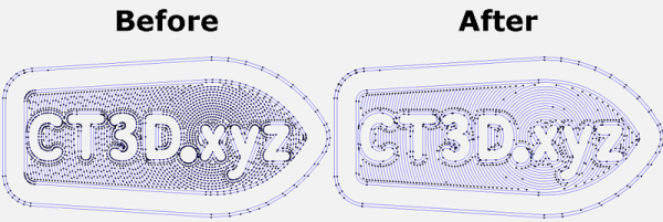
When the slicer software for a 3D printer model files into GCode, it’s essentially creating a sequential list of connected line segments, organized by layer. But when the features of the original model are dense, or when the model is representing small curves, slicers end up creating a proliferation of teeny segments to represent this information.

This is just the nature of the beast; lots of detail translates into lots of teeny segments. Unfortunately, some printers actually struggle to print these models at the desired speeds, not because of some mechanical limitation, but because the processor cannot recalculate the velocities of these segments fast enough. The result is that some printers simply stutter or slow down the print, resulting in print times that are much higher than they should be.

Enter Arc Welder, a GCode compression tool written by [FormerLurker] that scrutinizes GCode files, hunts for these tiny segments, and attempts to replace contiguous clusters of them with a smaller number of arcs. The result is that the number of GCode commands needed to represent the model drop dramatically as connected clusters of segment commands become single arc commands.

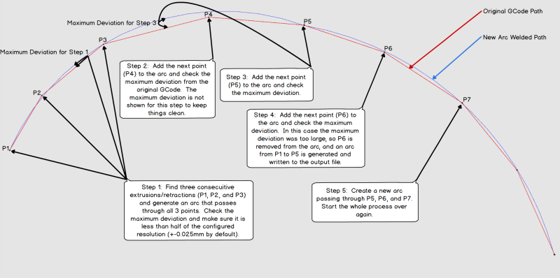
“Now wait”, you might say, “isn’t an arc an approximation of these line segments?” And yes–you’re right! But here lies the magic behind Arc Welder. The program is written such that arcs only replace segments if (1) an arc can completely intersect all the segment-to-segment intersections and (2) the error in distance between segment and arc representation is within a certain threshold. These constraints act such that the resulting post-processing is true to the original to a very high degree of detail.

A concise description of Arc Welder’s main algorithm as pulled from the docs

This whole program operates under the assumption that your 3D printer’s onboard motion controller accepts arc commands, specifically G2 and G3. A few years ago, this would’ve been uncommon since, technically, 3D printing and STL file only requires moving in straight line segments. But with more folks jumping on the bandwagon to use these motion control boards for other non-printing applications, we’re starting to see arc implementations on boards running Marlin, Smoothieware, and the Duet flavor of RepRap Firmware.

For the curious, this program is kindly both well documented on operating principles and open source. And if [FormerLurker] seems like a familiar name before–you’d be right–as they’re also the mind behind Octolapse, the 3D printing timelapse tool that’s a hobbyist crowd favorite. Finally, if you give Arc Welder a spin, why not show us what you get in the comments?

Thanks for the tip [ImpC]!