Stuck Designing Two-Layer PCBs? Give Four Layers A Try!

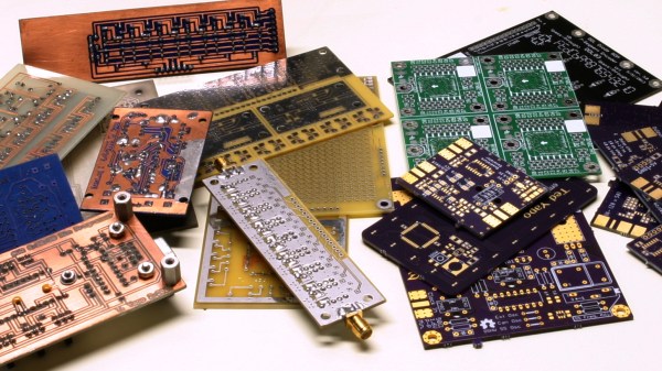
Many readers are certainly familiar with the process for home-etching of PCBs: it’s considered very straightforward, if a little involved, today. This was not the case in my youth, when I first acquired an interest in electronics. At that time, etching even single-sided boards was for “advanced” hobbyists. By the time I started etching my own PCBs, the advanced hobbyists were on to double-sided home-etched boards — the only type not pictured above, because I couldn’t find the one successful example I ever created. I later saw the rise of “bare bones” fabricated PCBs: professionally made fixed size boards with plated-through holes, but no soldermask or silkscreen. Eventually, this gave way to the aggregating PCB services we have now with full two-layer boards, complete with soldermask and silkscreen.

Today, the “advanced” hobbyist may be using four-layer boards, although the four-layer adoption rate is still relatively low – OSH Park produces around 90% two-layer and 10% four-layer, for instance. I think this will inevitably increase, as has been the case with all the previous technologies: the advanced eventually becomes the mainstream. Each of the previous shifts has brought easier design and construction as well as improved performance, and the same will be true as four layers becomes more commonplace.

So, let’s take a look at designing four-layer PCBs. If you’ve never considered one for any of your designs, you may be pleasantly surprised at what little extra cost is involved for all the benefits you gain. Continue reading “Stuck Designing Two-Layer PCBs? Give Four Layers A Try!”

Making The World’s Fastest 555 Timer, Or Using A Modern IC Version

If you’re not familiar with the 555 timer, suffice it to say that this versatile integrated circuit is probably the most successful ever designed, and has been used in countless designs, many of which fall very far afield from the original intent. From its introduction, the legendary 555 has found favor both with professional designers and hobbyists, and continues to be used in designs from both camps. New versions of the IC are still being cranked out, and discrete versions are built for fun, a temptation I just couldn’t resist after starting this article.

If you think all 555s are the same, think again. Today, a number of manufacturers continue to produce the 555 in the original bipolar formulation as well as lower-power CMOS. While the metal can version is no longer available, the DIP-8 is still around, as are new surface-mount packages all the way down to the chip-scale. Some vendors have also started making simplified variants to reduce the pinout. Finally, you can assemble your own version from a few parts if you need something the commercial offerings won’t do, or just want a fun weekend project. In my case, I came up with what is probably the fastest 555-alike around, although I spared little expense in doing so.

Follow along for a tour of the current state of the 555, and maybe get inspired to design something entirely new with this most versatile of parts.

Continue reading “Making The World’s Fastest 555 Timer, Or Using A Modern IC Version”

Ask Hackaday: How Do You Draw Schematics?

The lingua franca of electronic design is the schematic. I can pick up a datasheet written in Chinese (a language I do not read or speak) and usually get a half-decent idea of what the part is all about from the drawings. Unfortunately, even as my design experience has grown over the years, I haven’t quite learned to think in schematics — I need to see it on paper (or on a screen) to analyze a circuit. Whether it’s literally on the back of an envelope or sketched in the condensation on the shower stall, actually drawing a design or idea makes a huge difference in being able to understand it. And, if you’ve ever tried to explain a circuit without a schematic — in an on-line forum or over the phone, for instance — you know how difficult it is.

So, given the importance of the schematic for design and communication, you’d think choosing a tool to draw them would be an easy task. Not so. There are dozens of choices, from dedicated schematic drawing programs to using the schematic-capture facilities of simulation or PCB design tools, or even old-fashioned pencil-and-paper and its modern equivalents. Each one has its pros and cons, and may be better suited to one specific application, but you have to choose something.

So, readers of Hackaday, what do you use to convey your electronic design ideas to the world?

Continue reading “Ask Hackaday: How Do You Draw Schematics?”

A 3D Printed Blooming Rose For (Next) Valentines Day

Inspiration runs on its own schedule: great ideas don’t always arrive in a timely manner. Such was the case with [Daren Schwenke]’s notion for creating a 3D-printed blooming rose for his valentine, a plan which came about on February 13. Inspired by [Jiří Praus]’s animated wireframe tulip, [Daren] figured he could make a rose from clear printed petals colored by RGB LEDs. 24 hours seemed tight but sufficient, so he diligently set to work, but – after a valiant effort – finally had to extend the schedule. It’s now more than a month later, and tweaks to the design continue, but the result is nothing short of spectacular.

We first saw a discussion of the idea over on Hack Chat, and followed as it evolved into a project on hackaday.io. There, you can read the full details of the trials and tribulations that had to be endured to make this project happen. From a printer that wouldn’t boot, through testing PLA, TPU, and nylon filament, trying a number of different approaches for springs and hinges to operate the petals, and wiring the delicate DotStar LEDs with magnet wire, you can get a really good sense of the amount of experimentation it takes to complete a project like this. If you know anyone who still thinks 3D printing is as easy as clicking a button, send them over to read the logs on this project.

An early try at forming PLA petals

What finally materialized is a terrific combination of common hacker technologies. The petals are printed flat in nylon, then formed over a hot incandescent chandelier bulb. The stem and leaves are also printed, but the side stem has a piece of magnet wire embedded in the print as a capacitive touch sensor; when the leaf is touched, the rose blossom opens or closes. Magnet wire for the LEDs and a connecting rod for the mechanics run through the main stem to the base, where a 9g servo is responsible for controlling the bloom. The whole thing is controlled, naturally, with an Arduino. To move the project along a little more quickly, [Daren] enlisted the help of another Hack Chat denizen, [Morning.Star], who did an amazing job on the software without any access to the actual hardware.

Be sure to check out the video of the rose in action, after the break.

Continue reading “A 3D Printed Blooming Rose For (Next) Valentines Day”

A DIY Slip Roll On The Cheap

When you need to roll sheet or thin flat bar stock into an arc, you need a rolling machine, also known as a slip roll. If you’ve priced these lately, you’ll know that they can be rather expensive, especially if you are only going to use them for one or two projects. While building a fenced enclosure for his dog, [Tim] realized he could use steel fence posts and connectors to build his own slip roll for much less, and posted a video about it on his YouTube channel.

The key realization was that not only are the galvanized posts cheap and strong, but the galvanized coating would act as a lubricant to reduce wear, especially when augmented with a bit of grease. The build looks pretty straightforward, and a dedicated viewer could probably re-create a similar version with little difficulty. The stock fence connectors serve double-duty as both fasteners and bushings for the rollers, and a pair of turnbuckles supplies tension to the assembly.

The one tricky part is the chain-and-sprocket linkage which keeps the two bottom rollers moving in tandem. [Tim] cut sprockets from some plate steel with his plasma cutter, but mentions that similar sprockets can be found cheaply online and only need to be modified with a larger hole. Although most of the build is held together with set screws in the fence post fittings, the sprockets appear to be welded to the galvanized pipe. We’re sure [Tim] knows that welding galvanized steel can lead to metal fume fever, so we were hoping the video would caution viewers to remove the zinc coating on those parts before welding.

[Tim] demonstrates forming some 4 mm flat steel into circles, and the operation seems easy enough, especially given the inexpensive nature of this build. Overall, this seems like the sort of thing we could see ourselves trying on a lazy Saturday afternoon – it certainly seems like more fun than building a fence with the parts, so be sure to check out the video, after the break.

Continue reading “A DIY Slip Roll On The Cheap”

Do You Know Where Your Drone Is Headed? HJWYDK Article Explores Limits Of MEMS Sensors

Knowing in what absolute direction your robot is pointed can be crucial, and expensive systems like those used by NASA on Mars are capable of calculating this six-dimensional heading vector to within around one degree RMS, but they are fairly expensive. If you want similar accuracy on a hacker budget, this paper shows you how to do it using cheap MEMS sensors, an off-the-shelf motion co-processor IC, and the right calibration method.

The latest article to be published in our own peer-reviewed Hackaday Journal is Limits of Absolute Heading Accuracy Using Inexpensive MEMS Sensors  (PDF). In this paper, Gregory Tomasch and Kris Winer take a close look at the heading accuracy that can be obtained using several algorithms coupled with two different MEMS sensor sets. Their work shows that when properly used, inexpensive sensors can produce results on par with much more costly systems. This is a great paper that illustrates the practical contributions our community can make to technology, and we’re proud to publish it in the Journal.

Continue reading “Do You Know Where Your Drone Is Headed? HJWYDK Article Explores Limits Of MEMS Sensors”

Make XKCD-Style Plots From Python

[Randall Munroe] certainly understands the power of graphical representation of data. The humorous plots in his xkcd webcomic are one of the favorite parts for many readers. Their distinctive, Tufteian style delivers the information – in this case, a punch line – without excessive decoration. To be honest, we can’t get enough of them. A recent reddit thread reminded us that you can generate a similar look for your own data (humorous or otherwise) in Python using Matplotlib.

If you already have a plot generated with Matplotlib, activating xkcd-mode is as simple as calling a method on the pyplot object:

matplotlib.pyplot.xkcd()

The documentation recommends that you install the “Humor Sans” font for best effect. On one of our linux boxes, we were able to do this with a simple:

sudo apt-get install fonts-humor-sans

There will undoubtedly be similar incantations for other operating systems. It’s really that simple. In fact, the featured image above was generated with this minimal script:

#!/usr/bin/env python3

import numpy as np
import matplotlib.pyplot as plt

x = np.linspace(0, 1, 100)
y = (x > 0.5) * (x - 0.5)

plt.xkcd(scale=5, length=400)
plt.xticks([])
plt.yticks([])
plt.ylabel('Downloads of "humor sans" font')
plt.text(0, 0.25, 'Article on xkcd() published')
plt.plot(x, y)
plt.plot([0.3, 0.475], [0.2, 0.025], 'black')
plt.gca().set_aspect(2*9/16)
plt.savefig('xkcd_plot.png', dpi=300)

Beyond generating humorous graphs for those with little artistic talent, these plots can also be used instead of hand-drawn sketches to indicate a simple model or expected result. The comic look of the plots conveys the idea that they don’t represent actual data, perhaps only a concept. We saw this done at one of the talks at the Hackaday SuperConference 2018.

We’ve also covered some of the xkcd comics before, such as when they subtly dissed Arduino back in 2010, before that was cool.