Giant 3D Prints Piece-by-Piece

While FDM printers have gotten bigger lately, there’s almost always going to be a part that is bigger than your bed. The answer? Break your design into parts and assemble them after printing. However, the exact method to do this is a bit of a personal choice. A mechanical engineering student wrote:

After researching the state of the art as well as your ideas here on reddit, I realized, that there are almost no universal approaches to divide a large part and join the pieces which maintain mechanical strength, precisely position each segment, and also counteract tolerances due to the FDM-process.

Therefore I tried to develop a universal method to segment large trim parts, additively manufacture each segment and finally join those segments to form the desired overall part.

The result is a research paper you can download for free. The method focuses on thin parts intended as automotive trim, but could probably be applied to other cases.

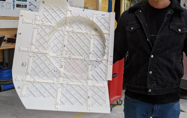
You can read about the thought process, but the final result was a joggle — a joint made with a rabbet and tongue. Adhesive holds it together, but the joint offers advantages in constraining the final product and the transmission of force in the assembly. Judging by the picture, the process works well. It would be interesting to see slicer software develop the capability to segment a large model using this or a similar technique.

Of course, you can just build a bigger printer, at least to a point. It seems, though, that that point is pretty big.

Improve Your Front Panels

For many of us, the bane of electronic projects is making a professional-looking enclosure. Sure, 3D printing has made it easier to make the actual enclosure, but there’s still the problem of labeling it. [Richard Langner] has the answer with something he calls easy front panels. You can read about it or watch the tutorial video below.

The concept is easy enough. You create your beautiful artwork in your choice of graphics programs. The example uses Inkscape, but you could do it in anything, even PowerPoint. You print it out and cut it to size. You could, of course, print it in color or — as the example does — color it in by hand.

Continue reading “Improve Your Front Panels”

Art of 3D printer in the middle of printing a Hackaday Jolly Wrencher logo

3D Printering: Getting Started With Universal Bed Leveling

Last time we talked about how Marlin has several bed leveling mechanisms including unified bed leveling or UBL. UBL tries to be all things to all people and has provisions to create dense meshes that model your bed and provides ways for you to adjust and edit those meshes.

We talked about how to get your printer ready for UBL last time, but not how to use it while printing. For that, you’ll need to create at least one mesh and activate it in your startup code. You will also want to correctly set your Z height to make everything work well. Continue reading “3D Printering: Getting Started With Universal Bed Leveling”

This DIY Microscope Design Is All Wet

[Robert Murray-Smith] wanted to recreate how some ancient microscopes worked: with a drop of water as a lens. The idea is that the meniscus of a drop of water will work as a lens. This works because of surface tension and by controlling the attraction of the water to the surface,  you can actually form convex and concave surfaces.

What’s interesting is that this doesn’t require a lot of equipment. Some plastic, a hole punch, some pens, a flashlight, and some other odds and ends. Then it’s just a matter of grabbing some puddle water and examining the critters inside. Of course, with a single lens, these are more properly magnifying glasses. Some claim that people in China built such instruments thousands of years ago. [Robert] mentions [Antonie van Leeuwenhoek] as the father of the microscope, although he wasn’t the first to build such a device. He did create amazing glass lenses using a method he kept secret but has been worked out using modern science.

It is hard to see much through the camera, but it clearly was magnifying. Not a bad little rainy day kid’s project since you probably have everything you need on hand. We wonder what other readily-available things you could image with a device like this.

Of course, if you want to build a real microscope, the designs are out there. You can even make one using — mostly — LEGO.

Continue reading “This DIY Microscope Design Is All Wet”

Pico Does PID

If you wanted to, say, control a temperature you might think you could just turn on a heater until you reach the desired temperature and then turn the heater off. That sort of works, but it is suboptimal — you’ll tend to overshoot the goal and then as the system cools down, you’ll have to catch up and the result is often a system that oscillates around the desired value but never really settles on the correct temperature. To solve that, you can use a PID — proportional integral derivative — loop and that’s what [veebch] has done with a Rasberry Pi PICO and Micropython.

The idea is to control an output signal based on the amount of difference between the actual temperature and the desired temperature (the proportional error). In addition, the amount is adjusted based on the long term error (integral) and any short term change (the derivative). You can also see a video about using the control loop to make a better sous vide burger, below. Continue reading “Pico Does PID”

Microwave Sampler Is Like Time Domain Mixer

[Gregory] is building some microwave gear and wanted to convert a 3.3 GHz signal to a 12 MHz intermediate frequency. You might think of using a mixer, but you’d need a local oscillator of nearly 3.3 GHz which is not only hard to build, but also will be very close to the signal of interest which is not a great idea. Instead, [Gregory] opted for a sampler, which uses an effect you usually try to avoid — aliasing — to allow downconversion with a much smaller local oscillator. You can see the design in the video below.

In the case of converting 3.3 GHz to 12 MHz, the local oscillator is around 100 MHz. How does that work? Watch the video and find out. The final project will triple the 3.3 GHz signal and we presume the 12 MHz downconvert is to easily phase lock the frequency using a PLL (phase-locked loop).

Continue reading “Microwave Sampler Is Like Time Domain Mixer”

Impedance Matching Revisited

If you are an old hand at RF design, you probably have a good handle on matching impedance. However, if you are just getting started with RF, [FesZ Electronic]’s latest video series on lossless impedance matching is well worth watching.

Matching is important for several reasons. Maximum power transfer occurs when the source and load impedance match. Also, at RF, mismatched impedance can cause reflections which, again, robs you of useful power. The video covers some math and then moves on to LTSpice to simulate a test circuit. But the part you are really waiting for — the practical circuits — is about 15 minutes in. Since the values you need are often oddball, [FesZ] makes his own adjustable inductors and uses a trimmer capacitor to adjust the actual capacitance value.

This is a big topic, but the first video is a great introduction blending theory, simulation, and hands-on. A great way to get started with a very fundamental RF design skill.

We’ve worked on explaining all this before if you want a second take on it. If you want to understand why mismatched impedance leads to less power delivery, we’ve done that, too.

Continue reading “Impedance Matching Revisited”