Is That A Large Smartwatch? Or A Tiny Cray?

While we aren’t typically put off by a large wristwatch, we were taken a bit aback by [Chris Fenton]’s latest timepiece — if you can call it that. It’s actually a 1/25th-scale Cray C90 worn as a wristwatch. The whole thing started with [Chris] trying to build a Cray in Verilog. He started with a Cray-1 but then moved to a Cray X-MP, which is essentially a Cray-1 with two extra address bits. Then he expanded it to 32 bits, which makes it a Cray Y-MP/C90/J90 core. As he puts it, “If you wanted something practical, go read someone else’s blog.”

The watch emulates a Cray C916 and uses a round OLED display on the top. While the move from 22 to 32 address bits sounds outdated, keep in mind the Cray addresses 64-bit words exclusively, so we’re talking access to 32 gigabytes of memory. The hardware consists of an off-the-shelf FPGA board and a Teensy microcontroller to handle mundane tasks like driving the OLED display and booting the main CPU. Interestingly, the actual Cray 1A used Data General computers for a similar task.

Of course, any supercomputer needs a super program, so [Chris] uses the screen to display a full simulation of Jupiter and 63 of its moons. The Cray excels at programs like this because of its vector processing abilities. The whole program is 127 words long and sustains 40 MFLOPs. Of course, that means to read the current time, you need to know where Jupiter’s moons are at all times so you can match it with the display. He did warn us this would not be practical.

While the Cray wouldn’t qualify as a supercomputer today, we love learning about what was state-of-the-art not that long ago. Cray was named, of course, after [Seymour Cray] who had earlier designed the Univac 1103, several iconic CDC computers, and the Cray computers, of course.

The ’80s Multi-Processor System That Never Was

Until the early 2000s, the computer processors available on the market were essentially all single-core chips. There were some niche layouts that used multiple processors on the same board for improved parallel operation, and it wasn’t until the POWER4 processor from IBM in 2001 and later things like the AMD Opteron and Intel Pentium D that we got multi-core processors. If things had gone just slightly differently with this experimental platform, though, we might have had multi-processor systems available for general use as early as the 80s instead of two decades later.

The team behind this chip were from the University of Califorina, Berkeley, a place known for such other innovations as RAID, BSD, SPICE, and some of the first RISC processors. This processor architecture would be based on RISC as well, and would be known as Symbolic Processing Using RISC. It was specially designed to integrate with the Lisp programming language but its major feature was a set of parallel processors with a common bus that allowed for parallel operations to be computed at a much greater speed than comparable systems at the time. The use of RISC also allowed a smaller group to develop something like this, and although more instructions need to be executed they can often be done faster than other architectures.

The linked article from [Babbage] goes into much more detail about the architecture of the system as well as some of the things about UC Berkeley that made projects like this possible in the first place. It’s a fantastic deep-dive into a piece of somewhat obscure computing history that, had it been more commercially viable, could have changed the course of computing. Berkeley RISC did go on to have major impacts in other areas of computing and was a significant influence on the SPARC system as well.

First Hubble Image Taken In New Single Gyro Pointing Mode

After Space Shuttle Atlantis’ drive-by repair of the Hubble Space Telescope (HST) in May of 2009, the end of the STS program meant that the space telescope had to fend for itself with no prospect for any further repair missions. The weakest point turned out to be the gyroscopes, with of the original six only three functioning until May 24th of 2024 when one failed and couldn’t be reset any more. To make the most out of the HST’s remaining lifespan, NASA decided to transition again to single-gyroscope operation, with the most recent imaging results showing that this enables HST to return to its science mission.

Although the HST has operated with a reduced number of gyroscopes before, while awaiting its (much delayed) 2009 Servicing Mission 4, this time around it would appear that no such aid is coming. Although HST is still very much functional even after recently celebrating its 34th year in space, there is a lot of debate about whether another servicing mission could be organized, or whether HST will be deorbited in a number of years. Recently people like [Jared Isaacman] have suggested ideas for an STS servicing mission, with [Jared] even offering to pay for the entire servicing mission out of pocket.

While there is an argument to be made that a Crew Dragon is a poor substitute for a Shuttle with its big cargo bay, airlock and robotic arm, it’s promising to see at least that for now HST can do what it does best with few compromises, while we may just see Servicing Mission 5 happening at some point before that last gyro kicks the bucket.

Adding Texture To 3D Prints

[3DJake] likes putting textures on 3D prints using things like patterned build plates and fuzzy skin. However, both of those techniques have limitations. The build plate only lets you texture the bottom, and the fuzzy skin texture isn’t easy to control. So he shows how to use Blender to create specific textures to produce things like wood-like or leather-like surfaces, for example. You can see how it works in the video below.

As [Jake] points out, you might be able to use other artistic programs to do this, but the kind of things we use like FreeCAD of Fusion360 aren’t going to cut it.

Continue reading “Adding Texture To 3D Prints”

Electronic Etch-A-Sketch, No Microcontroller Required

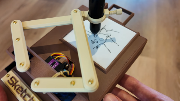
In a lot of ways, Etch-A-Sketch is the perfect toy; simple, easy to use, creative, endlessly engaging, and as a bonus, it’s completely mechanical. We find that last attribute to be a big part of its charm, but that’s not to say an electronic version of the classic toy can’t be pretty cool, especially when it’s done without the aid of a microcontroller.

This is one of those “because I can” projects that we always find so interesting, and more so because it wasn’t entirely clear to [BigZaphod] that he had the skills to pull it off. While his initial design centered around a bunch of 8×8 LED matrix displays and a 256×4-bit RAM chip, the rest of it was a lot of hand-waving. After a few experiments with addressing the LEDs, [Zaphod] started filling in the blanks with a refresh circuit using a 555 — naturally — and a pair of counters. Properly debounced encoders for the horizontal and vertical controls came next, along with more counters to track the cursor and a host of other circuits that ended up looking like a “one of each” selection from the 7400-series catalog.

While we do wish for a schematic on this one, it’s still a pretty enjoyable video, and the end product seems to work really well. The electronic version has a few features the original lacks, such as wrapping the cursor to the other side of the screen. We’d imagine that the buttons on the encoders could be put to work, too; perhaps a click could make it so you can move the cursor without leaving a trail behind. That might be a challenge to execute in logic, but then again, that was the point of the whole thing.

Still jonesing for that mechanical Etch-A-Sketch experience? Not a problem.

Continue reading “Electronic Etch-A-Sketch, No Microcontroller Required”

Arduino + TFT = Micro Star Chart

We always look at the round LCDs and wonder what to do with them other than, of course, a clock. Well, [shabaz] had a great idea: use it as a star map display. The project combines the Arduino, a round TFT, a GPS receiver, and some external flash memory to store data. You can get by without the GPS receiver or flash memory, but you’ll lose features if you do.

We like how he approached the problem. The project contains four major parts and he developed each part independently before integrating them into a whole. The four parts are: reading the GPS, driving the LCD, providing storage for star data, and determining the position of stars. The heavy lifting is done using some public domain code ported over. This code derives from a book called Astronomical Algorithms and uses the Yale Bright Star Catalog database.

The post mentions that the screen might well be a larger rectangular screen and we agree that would make this more usable. Now if you could cram it all into a watch, that might be different. If you want to play with the code, you can actually run the core on Linux. You’ll have to settle for a PNG output of the night sky, but that would be handy for debugging.

We have seen a star chart in a watch before. While this is more a star chart than a planetarium, we have no doubt the early planetarium builders would be suitably impressed.

Continue reading “Arduino + TFT = Micro Star Chart”

Ask Hackaday: How Do You Make Front Panels?

We’ll admit it. The closer a project is to completion, the less enthusiasm we have for it. Once the main design is clearly going to work on a breadboard, we’re ready to move on to the next one. We don’t mind the PCB layout, especially with modern tools. However, once the board is done, you have to do the case. Paradoxically, this was easier in the old days because you just picked some stock box, drilled some holes, and while it looked terrible, it was relatively easy.

Today, the bar is much higher. You’ll probably 3D print or laser cut an enclosure. If it looks no better than what you did in the 1970s, you won’t win many admirers. We routinely cover projects that could easily pass for commercial products. So how do you do it?

The Parts

The enclosure may even be the easy part. There are plenty of scripts and generators that will make you a nice box that meets your specifications. You can probably even get the holes made as you build. Back in the day, it was a challenge to cut odd-shaped holes for things like serial port connectors. Now, no problem. The printer or laser will just make a hole with any shape you like. You may even want to try a new angle on 3D printing.

Mounting the PCB isn’t that hard, either. With 3D printing, you can create standoffs, but even if you laser cut, you can easily use conventional standoffs. In a pinch, we’ve used long bolts with nuts.

The real problem, it seems to us, is the front panel. Only Star Trek can get away with front panels containing a bunch of knobs and dials with no markings. And although we call them “front” panels, sometimes you need markings on the back or even the sides, too. Continue reading “Ask Hackaday: How Do You Make Front Panels?”