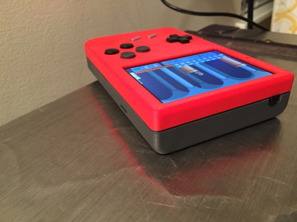
Reverse-Engineering A Game Boy Clone’s Boot ROM

[nitro2k01] got his hands on a Game Fighter, a clone of the original Game Boy. While there’s a ton of information about the boot ROM and operation of the original Game Boy, not much is known about these clones. [nitro2k01] wanted to learn more, so he used a clock-glitching technique to dump the device’s ROM and made some interesting discoveries about its copyright protection and boot process along the way.

Reading the contents of the Game Boy ROM is a bit challenging. The ROM is readable while booting, but afterwards the address space of the ROM is remapped for interrupt vectors and other uses. There are a couple of methods to get around this, but the simplest method involves glitching the crystal by grounding one of its leads. This causes the CPU to jump to random locations in memory. Eventually the CPU will jump to a location where the boot ROM is accessible (if you’re lucky!).

Although [nitro2k01]’s clone can run the same games as the Game Boy, it has a different boot ROM and also has some significant hardware differences. [nitro2k01] managed to use a modified version of the crystal-grounding technique to glitch his clock and dump the clone’s boot ROM. He found that the clone uses an unusual variation on the Game Boy’s copyright-checking technique, along with some other oddities. [nitro2k01] also posted a disassembly of the boot ROM, which he explains in detail.

Thanks for the tip, [Ove].

ArTICam Interfaces Game Boy Camera With TI Calculators

[Christopher Mitchell] has given Texas Instruments calculators the ability to capture images through a Game Boy Camera with ArTICam. First introduced in 1998, The Game Boy Camera was one of the first low-cost digital cameras available to consumers. Since then it has found its way into quite a few projects, including this early Atmel AT90 based hack, and this Morse code transceiver.

TI calculators don’t include a Game Boy cartridge slot, so [Christopher] used an Arduino Uno to interface the two. He built upon the Arduino-TI Calculator Linking (ArTICL) Library  to create ArTICam. Getting the Arduino to talk with the Game Boy Camera’s M64282FP image sensor turned out to be easy, as there already are code examples available. The interface between the camera sensor and the Arduino is simple enough. 6 digital lines for an oddball serial interface, one analog sense line, power and ground. [Christopher] used a shield to solder everything up, but says you can easily get away with wiring directly the Arduino Uno’s I/O pins. The system is compatible with the TI-83 Plus and TI-84 Plus family of calculators. Grabbing an image is as simple as calling  GetCalc(Pic1) from your calculator program.

So, If you have an old calculator lying around, give it a try to enjoy some 128×123-pixel grayscale goodness!

HDMI Out With A Brick Game Boy

A few years ago, some vastly clever people figured out how to listen in on the LCD display on the classic brick Game Boy from 1989. There have been marked improvements over the years, including a few people developing VGA out for the classic Game Boy. Now, the bar has been raised with an HDMI adapter for the Game Boy, designed in such a way that turns everyone’s favorite battery hog into a portable console.

Your classic beige or cleverly named Color Game Boy is composed of two halves. The rear half contains all the important circuitry – the CPU, cartridge connector, and the rest of the smarts that make the Game Boy game. The front half is fairly simple in comparison, just an LCD and a few buttons. By designing an adapter that goes between these two halves, [Zane] and [Joshua] were able to stuff enough circuitry inside the Game Boy to convert the signals going to the LCD to HDMI. Plug that into your TV, and you have a huge modern version of the Super Game Boy, no SNES required.

The HDMIBoy also breaks out the buttons to the classic NES controller connector. With HDMI out and a controller input, the old-school Game Boy become a portable if somehow even more brick-like console.

A Raspberry Pi In A Game Boy Advance SP

It’s not the biggest use of a Raspberry Pi, but running emulators for old game systems is by far the most visible use of the Pi. In fact, putting Pis inside old game systems has led to a resurgence of case modding not seen since the heyday of the Mini-ITX craze of the early ‘aughts.

You’d think every possible Pi casemod had been done by now, but [frostedfires] is still raising the bar with a Pi casemod that stuffs a clone of everyone’s favorite credit card sized computer into a Game Boy Advance SP.

[frostedfires] isn’t using a real Raspi from The Foundataion. Instead, he found the Odroid W, a raspi compatible board that’s about half the size of a model B. It still has everything needed to complete the build – analog video out, a reasonable Linux system, and enough processing power to run Quake III. Right now, [frostedfires] has the screen working – that was taken from a car backup camera. Other than that, the only portion of the build left to go is a few buttons.

This is officially the smallest derivative casemod we’ve ever seen. the previous record holder was the still tiny Game Boy Pocket build from last summer. That build required heavy modifications to the Model B board, though, so if you’re aiming for a smaller build, the Odroid is the way to go.

Thanks to the Bacman forums for yet another great build.

The Tale Of Two Wearable Game Boys

We’re well past the time when Halloween costume submissions stop hitting the tip line, but like ever year we’re expecting a few to trickle in until at least Thanksgiving. Remember, kids: documentation is the worst part of any project.

[Troy] sent us a link to his wearable Game Boy costume. It’s exactly what you think it is: an old-school brick Game Boy that [Troy] wore around to a few parties last weekend. This one has a twist, though. There’s a laptop in there, making this Game Boy playable.

The build started off as a large cardboard box [Troy] covered with a scaled-up image of everyone’s favorite use of AA batteries. The D-pad and buttons were printed out at a local hackerspace, secured to a piece of plywood, and connected to an Arduino Due. The screen, in all its green and black glory, was taken from an old netbook. It was a widescreen display, but with a bezel around the display the only way to tell it’s not original is from the backlight.

Loaded up with Pokemon Blue, the large-scale Game Boy works like it should, enthralling guests at wherever [Troy] ended up last Friday. It also looks like a rather quick build, and something we could easily put together when we remember it next October 30th.

[Troy] wasn’t the only person with this idea. A few hours before he sent in a link to his wearable Game Boy costume, [Shawn] sent in his completely unrelated but extremely similar project. It’s a wearable brick Game Boy, a bit bigger, playing Tetris instead of Pokemon.

[Shawn]’s build uses a cardboard box overlaid with a printout of a scaled-up Game Boy. Again, a laptop serves as the emulator and screen, input is handled by a ‘duino clone, and the buttons are slightly similar, but made out of cardboard.

Both are brilliant builds, adding a huge Game Boy to next year’s list of possible Halloween costume ideas. Videos of both below.

Continue reading “The Tale Of Two Wearable Game Boys”

The Game Boy Pocket Raspi Mod Puts All Others To Shame

There are hundreds – perhaps thousands – of builds out there on the Internet that put a Raspberry Pi in an enclosure with buttons meant solely for running emulators for old games. This one is unlike any other. Yes, it’s still basically a RetroPi emulator, but this Game Boy Pocket casemod goes beyond any remotely comparable build.

The Game Boy Pocket is incredibly small, but after sanding down the bosses on the inside of the case, gluing the battery door shut, and installing a bit of plastic over the cartridge slot, [WarriorRocker] was able to fit a Raspi inside. The buttons use the same PCB as the stock Game Boy, connected to a Teensy 2.0 board that simulates a USB keyboard.

With the two largest components taken care of, [Warrior] turned his attention to the sound, video and power. The display is a 2.5″ composite LCD that actually fits quite nicely behind the screen bezel. Audio is taken care of by a $3 audio amplifier, a new, smaller speaker, and a side-mounted pot stolen from the original Game Boy guts. There’s no chance on running this with the same 2xAAA cells the original Game Boy Pocket had, so [Warrior] somehow found space for a 2600mAh Li-Poly battery, a step-up regulator, and a charge circuit.

The result is a full-color RetroPi build capable of running for three hours before needing a recharge. All the classic Game Boy games are loaded onto the SD card along with select titles for other systems. The result is one of the best portabalized Raspi builds we’ve ever seen. Video below.

Continue reading “The Game Boy Pocket Raspi Mod Puts All Others To Shame”

Game Boy Vs. Electronic Shelf Labels

SANYO DIGITAL CAMERAWhile they’re probably rare as hen’s teeth in the US, there have been a few major stores around the world that have started rolling out electronic shelf labels for every item in the store. These labels ensure every item on a shelf has the same price as what’s in the store’s computer, and they’re all controlled by an infrared transceiver hanging on the store’s ceiling. After studying one of these base stations, [furrtek] realized they’re wide open if you have the right equipment. The right equipment, it turns out, is a Game Boy Color.

The shelf labels in question are controlled by a base station with a decidedly non-standard carrier frequency and a proprietary protocol. IR driver chips found in phones are too slow to communicate with these labels, and old PDAs like Palm Pilots, Zauruses, and Pocket PCs only have an IrDA chip. There is one device that has an active development scene and an IR LED connected directly to a CPU pin, though, so [furrtek] started tinkering around with the hardware.

The Game Boy needed to be overclocked to get the right carrier frequency of 1.25 MHz. With a proof of concept already developed on a FPGA board, [furrtek] started coding for the Game Boy, developing an interface that allows him to change the ‘pages’ of these electronic labels, or display customized data on a particular label.

There’s also a much, much more facepalming implication of this build: these electronic labels’ firmware is able to be updated through IR. All [furrtek] needs is the development tools for the uC inside one of these labels.

There’s a great video [furrtek] put together going over this one. Check that out below.

Continue reading “Game Boy Vs. Electronic Shelf Labels”