Russian Hacker Multiplies Value Of Boost Converter

We have a love/hate relationship with LiIon batteries. They pack all this power in such a small and light package. But for running 3.3 V devices, they’re cumbersome. They need to be stepped down a little bit when they’re fully charged at 4.2 V, but then they need to be stepped up at the end of their charge around 3.0 V.

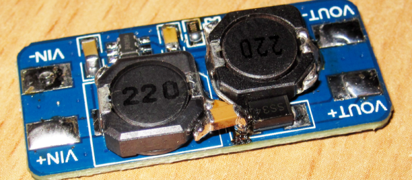
A simple boost or buck converter can’t do both jobs, although you’d be tempted because they can be purchased for peanuts online. So [Kirich] hacked cheap boost converters into the more capable SEPIC topology, which sell for nearly 10x as much. (Google translated version here.) The bottom line? With a little desoldering, a cut trace here and an extra inductor there, and [Kirich] had a very capable circuit that would maintain a constant 3.3 V output when the input swung between 1 V and 5 V.

95aa17
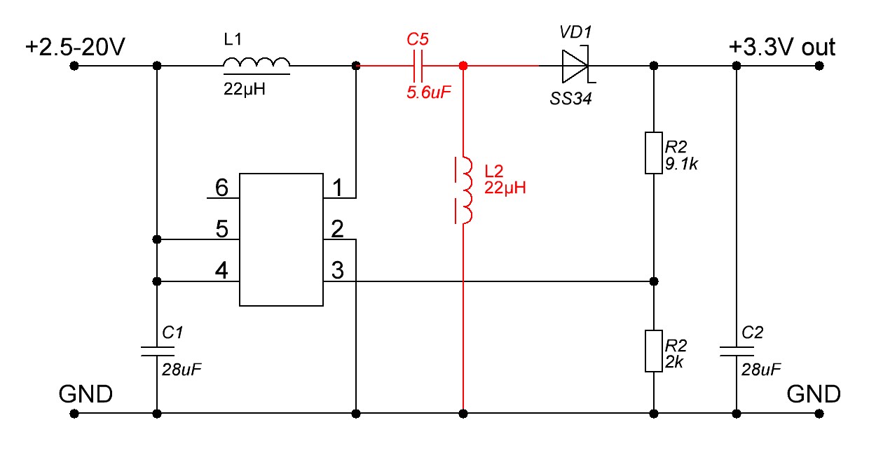
If SEPIC power converters are foreign to you, have a read through Maxim’s white paper on the subject. Basically, it’s a boost converter with a capacitor in the middle that lets the output voltage drop below the input voltage. An extra inductor keeps the output side of this capacitor at ground potential (on average).

If you want more detail, [Kirich] doesn’t disappoint. He tested his modifications in multiple configurations on two different models of boost converter. As you’d expect with power circuitry, layout and trace length matters, and [Kirich] took good notes. This is a great read for the frugal hacker, or anyone who’s interested in boost/buck converters.

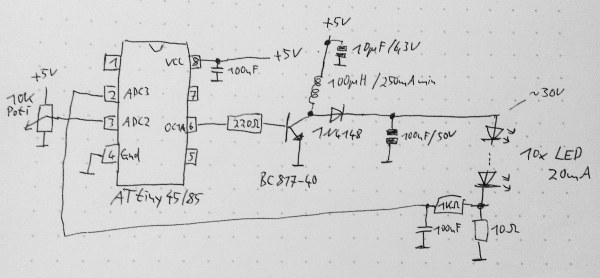
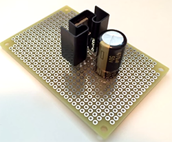
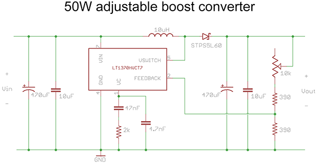
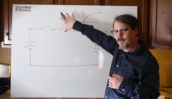
Speaking of boost/buck circuits, we’ve got some more links for you. This video from Sparkfun’s [Pete Dokter] is worth fifteen minutes, and if you want to get your hands really dirty in the construction of such circuits, this ATtiny-based boost converter circuit is fun to play with.

Thanks [kirillre4] for the great tip!

Schematic for a boost converter based on the ATtiny MCU

An ATtiny Boost Converter

This schematic is all you need to build your own voltage converter. [Lutz] needed a converter that could boost 5 V to 30 V to power a string of LEDs. The solution was to use low cost ATtiny85 and some passive components to implement a boost converter.

This circuit follows the classic boost converter topology, using the ATtiny85 to control the switch. The 10 ohm resistor is fed back into the microcontroller’s ADC input, allowing it to sense the output voltage. By measuring the output voltage and adjusting the duty cycle accordingly, the circuit can regulate to a specified voltage setpoint.

A potentiometer is used to change the brightness of the LEDs. The software reads the potentiometer’s output voltage and adjusts the voltage output of the circuit accordingly. Higher voltages result in brighter LEDs.

Of course, there’s many other ways to implement a boost converter. Most practical designs will use a chip designed for this specific purpose. However, if you’re interested in rolling your own, the source and LTSpice simulation files are available.

Afroman Demonstrates Boost Converters

If you need to regulate your power input down to a reasonable voltage for a project, you reach for a switching regulator, or failing that, an inefficient linear regulator. What if you need to boost the voltage inside a project? It’s boost converter time, and Afrotechmods is here to show you how they work.

In its simplest form, a boost converter can be built from only an inductor, a diode, a capacitor, and a transistor. By switching the transistor on and off with varying duty cycles, energy is stored in the inductor, and then sent straight to the capacitor. Calculating the values for the duty cycle, frequency, inductor, and the other various parts of a boost converter means a whole bunch of math, but following the recommended layout in the datasheets for boost and switching converters is generally good enough.

boostconverter

[Afroman]’s example circuit for this tutorial is a simple boost converter built around an LT1370 switching regulator. In addition to that there’s also a small regulator, diode, a few big caps and resistors, and a pot for the feedback pin. This is all you need to build a simple boost converter, and the pot tied to the feedback pin varies the duty cycle of the regulator, changing the output voltage.

It’s an extremely efficient way to boost voltage, measured by [Afroman] at over 80%. It’s also exceptionally easy to build, with just a handful of parts soldered directly onto a piece of perfboard.

Video below.

Continue reading “Afroman Demonstrates Boost Converters”

Building A Bipolar Supply From A Boost Converter

This DC-DC Bipolar PSU was developed for use with a guitar effects pedal. [Obsolete Technology] needed to source both positive and negative 15V. This is pretty easy to do if you’re converting from mains, but he wanted a solution that could work with a lower-voltage AC/DC wall wort or even from batteries.

The part that pulls it all together is the LT3467. It’s a switching power regulator which offers a range of features configured by the layout of a handful of external passive components. It can put out 80 mA on each line (positive and negative). Also extremely useful for this application is the chip’s high frequency operation. Depending on the version, it switches at 1.3 or 2.1 MHz. This is high enough that it will not introduce audible noise into the audio system.

We’ve got an exercise bike whose negative supply for the LCD is blown. We’re going to try build this circuit, trimming it for our voltage needs, and get the contrast working again.

[Thanks Olli]

An Introduction To DC Boost Converters

simple_boost_converter

If you are planning on creating some sort of Nixie tube display, you will undoubtedly need to find yourself a high voltage DC power supply. If you don’t want to add a transformer to your project, you can always opt to build a boost converter instead. [Andrew Moser] shows us just how easy it is to build one, discussing the theory behind simple boost converters along the way.

Boost converters are often driven by dedicated ICs, but in this case the PWM signal from an Arduino does the job just fine. [Andrew] covers the process of choosing the proper components for the circuit, discussing duty cycles and components to avoid lest your boost converter die an untimely death.

He shows us how to implement a feedback system to get a more precise output voltage, but as Lady Ada has shown us, an open loop works pretty well too.

For the beginners that want to just get things up and running, his instructions and code should be sufficient, but [Andrew] provides plenty of reference links for those looking to delve deeper into the subject.

AVR Boost Converter

avrboost

Over at SpriteMods, [sprite_tm] realized that a microcontroller could be used as a boost converter to power itself. A boost converter steps up voltage from a battery by switching the output of a coil. First, it is tied to ground so a magnetic field can build up in the coil. It is then released as a higher voltage than the input. Normally dedicated chips do this at an incredibly high frequency, but the PWM signal from an AVR works well enough. This can be used in low-power situations where space is an issue.

[via EMSL]

A Primer On Buck (and Boost) Converters

We all know that the reason the electrical system uses alternating current is because it’s easy to step the voltage up and down using a transformer, a feature which just isn’t possible with a DC system… or is it? Perhaps you’ve heard of mysterious DC-DC transformers before but never really wanted to look at the wizardry that makes them possible. Now, SparkFun Director of Engineering [Pete Dokter] has a tutorial which explains how these mysterious devices work.

Known as buck converters if they step the input voltage down and boost converters if they step the voltage up, [Pete] explains how these circuits exploit the properties of an inductor to resist changes in current flow. He goes into exquisite detail to explain how components like transistors or MOSFETs are used to switch the current flow to the inductor very rapidly, and just exactly what happens to the magnetic field which makes these devices possible.

The video gives a good amount of background knowledge if you’ve always wanted to understand these devices a little bit better. There are also a few projects floating around that exploit these devices, such as one that uses an AVR microcontroller to perform the switching for a small circuit, or another that uses the interesting properties of these circuits to follow the I-V curve of a solar panel to help charge a bank of batteries. The possibilities are endless!

Continue reading “A Primer On Buck (and Boost) Converters”