Reworking MT3608 Boost Converters For Lower Idle Current Draw

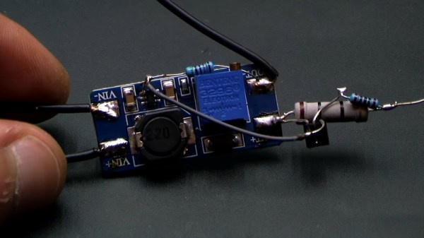
The MT3608 is a popular boost converter, able to easily step up DC voltages in useful ranges, at an incredibly low cost. Modules can be sourced from eBay for less than $2, built on a PCB, ready to go. One drawback of these modules, particularly when working with batteries, is the idle current draw, on the order of 1 to 1.5mA. Fear not, however — there is a workaround, courtesy of [Aka Kasyan]. (Video, embedded below.)

The trick is to modify the behavior of the converter when no load is connected. The enable pin of the boost converter is held low through a pull-down resistor, keeping the boost converter switched off. In this state, the output voltage is equal to the input voltage. A current sense resistor is then installed in the output path. When a load is connected, this causes a voltage drop across the current sense resistor. This is then used to switch a transistor, which then connects the enable pin to the positive rail, switching the converter on, leading to the full boosted output voltage being reached.

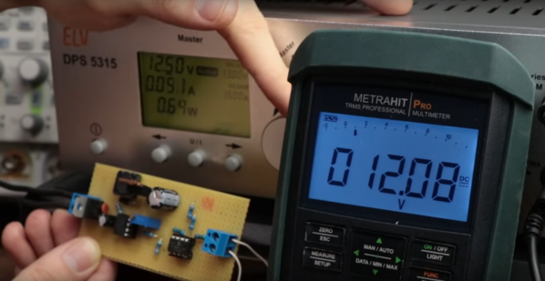
[Aya] reports that this drastically cuts the idle current draw, which is particularly useful for battery powered projects. It’s important to note that the current sense resistor must be appropriately sized for the given load, however. If you’re a little hazy on the background, fear not — we’ve discussed the nature of boost converters before. Video after the break.

[Thanks to Baldpower for the tip!]
Continue reading “Reworking MT3608 Boost Converters For Lower Idle Current Draw”

The Pros And Cons Of Microcontrollers For Boost Converters

It never fails — we post a somewhat simple project using a microcontroller and someone points out that it could have been accomplished better with a 555 timer or discrete transistors or even a couple of vacuum tubes. We welcome the critiques, of course; after all, thoughtful feedback is the point of the comment section. Sometimes the anti-Arduino crowd has a point, but as [Great Scott!] demonstrates with this microcontroller-less boost converter, other times it just makes sense to code your way out of a problem.

Built mainly as a comeback to naysayers on his original boost-converter circuit, which relied on an ATtiny85, [Great Scott!] had to go to considerable lengths to recreate what he did with ease using a microcontroller. He started with a quick demo using a MOSFET driver and a PWM signal from a function generator, which does the job of boosting the voltage, but lacks the feedback needed to control for varying loads.

Ironically relying on a block diagram for a commercial boost controller chip, which is probably the “right” tool for the job he put together the final circuit from a largish handful of components. Two op amps form the oscillator, another is used as a differential amp to monitor the output voltage, and the last one is a used as a comparator to create the PWM signal to control the MOSFET. It works, to be sure, but at the cost of a lot of effort, expense, and perf board real estate. What’s worse, there’s no simple path to adding functionality, like there would be for a microcontroller-based design.

Of course there are circuits where microcontrollers make no sense, but [Great Scott!] makes a good case for boost converters not being one of them if you insist on DIYing. If you’re behind on the basics of DC-DC converters, fear not — we’ve covered that before.

Continue reading “The Pros And Cons Of Microcontrollers For Boost Converters”

Nicely Engineered Boost Converter Powers Nixies From USB Charger

Love them or hate them, Nixies are here to stay. Their enduring appeal is due in no small part to the fact that they’re hardly plug-and-play; generating the high-voltage needed to drive the retro displays is part of their charm. But most Nixie power supplies seem to want 9 volts or more on the input side, which can make integrating them into the typical USB-powered microcontroller project difficult.

Fixing that problem is the idea behind [Mark Smith]’s 5-volt Nixie power supply. The overall goal is simple: 5 volts in, 170 volts out at 20 mA. But [Mark] paid special care to minimize the EMI output of the boost converter through careful design, and he managed to pack everything into a compact 14-cm² PCB. He subjected his initial design to a lot of careful experimentation to verify that he had met his design goals, and then embarked on a little tweaking mission in KiCad to trim the PCB’s footprint down by 27%. The three separate blog posts are well worth a read by anyone interested in learning about electronics design.

Now that [Mark] has his Nixie power supply, what will become of it? We can’t say for sure, but it’ll be a clock. It’s always a clock. Unless it’s a power meter or a speedometer.

Single Part Boost Converter Challenge (Completed)

[Josh] posed an interesting challenge. Create a boost converter that can light a blue LED using a nearly dead battery and one part. Well, we were skeptical until we saw he wasn’t counting an ATtiny processor as a part. You can see a video of the challenge, below.

The challenge has already been solved, so if you view the link, you might want to avoid the comments until you’ve had time to think about your own solution. We’ll confess, the first one we thought of was probably not workable for reasons [Josh] explains. The final answer neatly fits the criteria of a hack.

Continue reading “Single Part Boost Converter Challenge (Completed)”

The Science Behind Boost Converters

[Ludic Science] shows us the basic principles that lie behind the humble boost converter. We all take them for granted, especially when you can make your own boost converter or buy one for only a few dollars, but sometimes it’s good to get back to basics and understand exactly how things work.

The circuit in question is probably as simple as it gets when it comes to a boost converter, and is not really a practical design. However it helps visualize what is going on, and exactly how a boost converter works, using just a few parts, a screw, enameled wire, diode, capacitor and a push button installed on a board.

The video goes on to show us the science behind a boost converter, starting with adding a battery from which the inductor stores a charge in the form of an electromagnetic field. When the button is released, the magnetic field collapses, and this causes a voltage in the circuit which is then fed through a diode and charges the capacitor a little bit. If you toggle the switch fast enough the capacitor will continue to charge, and its voltage will start to rise. This then creates a larger voltage on the output than the input voltage, depending on the value of the inductor. If you were to use this design in a real life application, of course you would use a transistor to do the switching rather than a push button, it’s so much faster and you won’t get a sore finger.

This is very basic stuff,  but the video gives us a great explanation of what is happening in the circuit and why. If you liked this article, we’re sure you’ll love Hackaday’s own [Jenny List] explain everything you need to know about inductors.

(updated thanks to [Unferium] – I made a mistake about the magnetic field collapsing when the button is pressed , When in reality it’s when the button is released that this happens. Apologies for confusion.)

Continue reading “The Science Behind Boost Converters”

Boost Converter Functionality At Rock-Bottom Prices

Linear voltage regulators are pretty easy to throw into a project if something in it needs a specific voltage that’s lower than the supply. If it needs a higher voltage, it’s almost just as easy to grab a boost converter of some sort to satisfy the power requirements. But if you’re on a mission to save some money for a large production run, or you just like the challenge of building something as simply as possible, there are ways of getting voltages greater than the supply voltage without using anything as non-minimalistic as a boost converter. [Josh] shows us exactly how this can be done using a circuit known as a charge pump to drive a blue LED.

One of the cool things about AVR microcontrollers is that they can run easily on a coin cell battery and source enough current to drive LEDs directly from the output pins. Obviously enough, if the LED voltage is greater than the voltage of the power supply, this won’t work. That is, unless you have a spare diode and capacitor around to build a charge pump.

The negative charge pump works by charging up a capacitor that is connected to an AVR pin, with the other side between the LED and a garden-variety diode to ground. That results in a roughly (VCC – 0.7) volt difference across the capacitor’s plates. When the AVR pin goes low, the other side of the capacitor goes negative by this same amount, and this makes the voltage across the LED high enough to light up. Not only is this simpler than a boost converter, but it doesn’t need any bulky inductors to work properly.

Will this work for any load? Am I going to start any fires by overdriving the LED? Luckily, [josh] answers all of these questions and more on the project page, and goes into some detail on the circuit theory as well. Granted, the charge pump doesn’t have the fine control over the power supply that you can get out of a buck or boost converter (or any switch-mode power supply). But it does have good bang-for-the-buck.

A Buck-Boost Converter From The Ground Up

DC to DC conversion has come a long way. What was once took an electromechanical vibrator and transformer has been reduced to a PC board the size of a largish postage stamp that can be had for a couple of bucks on eBay. So why roll your own buck-boost converter for the ground up? Maybe because sometimes the best way to learn is by doing.

Continue reading “A Buck-Boost Converter From The Ground Up”