Switching Converter For EEPROM Programmer Taxes Solderless Breadboard

We all know that solderless breadboards have their limitations. All that stray capacitance can play hell with circuits, especially high-speed stuff, but they’re so darn useful that avoiding them in favor of some other prototyping method can be really hard. So we often just forge ahead, plugging in our parts and hoping for the best

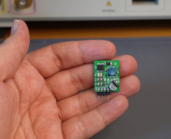
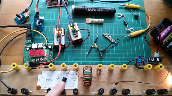
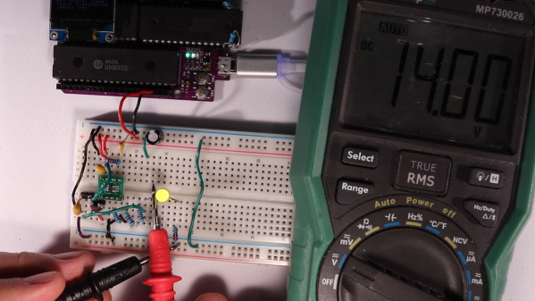
A recent veteran of the breadboard battle is [Anders Nielsen], who kicked off a new project by prototyping this high-voltage boost converter on a breadboard, with mixed results. The project is a scratch-built programmer for old-school ROM chips, a task normally farmed out to a dedicated programmer, but where’s the sport in that? Besides, this is the future, and generating the 12 to 14 volts needed should be a snap. And it would be, except for the fact that his chosen chip, a MIC2288 switching boost regulator, is only available in an SMD package. Getting the chip and a few other SMD support components onto breadboard-compatible breakouts proved to be challenging, and getting it working once it was there was even more work.

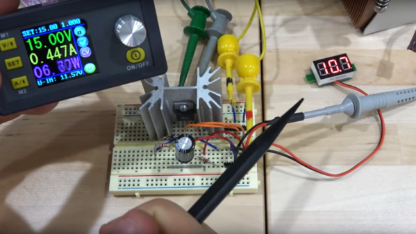
A lot of the trouble was down to simple breadboarding errors, but the big problem was the input capacitance, which [Anders] had to fiddle with quite a bit to get the converter to 14 volts. The current maxes out at about 25 mA before the voltage starts dropping, which just might be enough to burn those old chips, so we’ll call this a provisional win and see what happens when he builds the rest of the programmer.

[Anders]’ experience here raises a good question: what’s the best way to prototype using fussy SMD components? PCBs are cheap enough that it’s tempting to go straight to one, but swapping parts in and out like he had to do here to get everything just right would be much harder that way. We’re not sure we know the answer, but we’re pretty sure we’ll hear your thoughts on that in the comments section.

Continue reading “Switching Converter For EEPROM Programmer Taxes Solderless Breadboard”

Buck Converter Takes 8V To 100V

For those living before the invention of the transistor, the modern world must appear almost magical. Computers are everywhere now and are much more reliable, but there are other less obvious changes as well. Someone from that time would have needed a huge clunky machine like a motor-generator set to convert DC voltages, but we can do it with ease using a few integrated circuits. This one can take a huge range of input voltages to output a constant 5V.

The buck converter was designed by [hesam.moshiri] using a MP9486 chip. While it is possible to use a multipurpose microcontroller like something from Atmel to perform the switching operation needed for DC-DC converters, using a purpose-built chip saves a lot of headache. The circuit was modified a little bit to support the higher input voltage ranges and improve its stability and reliability. The board is assembled in an incredibly tiny package with inputs and outputs readily accessible, so it would be fairly simple to add one into a project rather than designing it from scratch.

Even though buck converters, and other DC converters like boost and the mysterious buck-boost converter, seem like magic even to us, there is some interesting electrical theory going on if you’re willing to dive into the inner workings of high-frequency switching. Take a look at this explanation we featured a while back to see more about how buck converters, the more easily understood among them, work.

Trouble With The Texas Power Grid As Cold Weather Boosts Demand, Knocks Out Generators

It comes as something of a shock that residents of the Lone Star State are suffering from rolling power blackouts in the face of an unusually severe winter. First off, winter in Texas? Second, isn’t it the summer heat waves that cause the rolling blackouts in that region?

Were you to mention Texas to a European, they’d maybe think of cowboys, oil, the hit TV show Dallas, and if they were European Hackaday readers, probably the semiconductor giant Texas Instruments. The only state of the USA with a secession clause also turns out to to have their own power grid independent of neighboring states.

An accurate and contemporary portrait of a typical Texan, as understood by Europeans. Carol M. Highsmith, Public domain.

Surely America is a place of such resourcefulness that this would be impossible, we cry as we watch from afar the red squares proliferating across the outage map. It turns out that for once the independent streak that we’re told defines Texas may be its undoing. We’re used to our European countries being tied into the rest of the continental grid, but because the Texan grid stands alone it’s unable to sip power from its neighbours in times of need.

Let’s dive into the mechanics of maintaining an electricity grid, with the unfortunate Texans for the moment standing in as the test subject.


Continue reading “Trouble With The Texas Power Grid As Cold Weather Boosts Demand, Knocks Out Generators”

Circuit VR: Simple Buck Converters

The first thing I ever built without a kit was a 5 V regulated power supply using the old LM309K. That’s a classic linear regulator like a 7805. While they are simple, they waste a lot of energy as heat, especially if the input voltage goes higher. While there are still applications where linear regulators make sense, they are increasingly being replaced by switching power supplies that are much more efficient. How do switchers work? Well, you buy a switching power supply IC, add an inductor and you are done. Class dismissed. Oh wait… while that might be the best way to do it from a cost perspective, you don’t really learn a lot that way.

In this installment of Circuit VR, we’ll look at a simple buck converter — that is a switching regulator that takes a higher voltage and produces a lower voltage. The first one won’t actually regulate, mind you, but we’ll add that in a future installment. As usual for Circuit VR, we’ll be simulating the designs using LT Spice.

Interestingly, LT Spice is made to design power supplies so it has a lot of Linear Technology parts in its library just for that purpose. However, we aren’t going to use anything more sophisticated than an op amp. For the first pass, we won’t even be using those.

Continue reading “Circuit VR: Simple Buck Converters”

Buck Converter Efficiency

We always appreciate when someone takes the time to build something and then demonstrates what different design choices impact using the real hardware. Sure, you can work out the math and do simulations, but there’s something about having real hardware that makes it tangible. [Julian Ilett] recently posted two videos that fit this description. He built a buck converter and made measurements about its efficiency using different configurations.

The test setup is simple. He monitors the drive PWM with a scope and has power meters on the input and output. That makes it easy to measure the efficiency since it is just the ratio of the power output to input. You can see the two videos, below.

Continue reading “Buck Converter Efficiency”

A Li-Ion Booster Pack, Done Right

We’re all used to battery booster packs containing a Li-ion or Li-poly cell and a little inverter circuit, they are a standard part of 21st century daily survival for those moments when smartphone battery lives don’t perform as advertised. But how many of us have considered what goes into them, and further how many of us have sought to produce the best one possible rather than a unit built at the lowest price?

It’s a course [Peter6960] has followed, producing a PCB that sits on the back of an 18650 cell holder. It follows the work of [GreatScott] in particular in its use of the TP4056 charger, MT3608 boost converter, and FS312F protection ICs. Many commercial modules omit any protection circuit, and the FS312F is of particular interest because it has a low 2.9V cut-off voltage that should lengthen the life of the cell. Files for the PCB can be found in a zip file hosted on Google Drive.

You might think that there was nothing new that could be learned about a Li-ion battery booster, but it’s always worth a look at a well-executed piece of work. We noticed he refers to Li-poly cells while using what appears to be a Li-ion 18650 cell. Most likely this is merely an oversight.

There is a lot to know about the characteristics and safety of the lithium-chemistry rechargeables, you may find [Sean Boyce]’s article on the subject to be an interesting read.

Cleaning Up A Low-Cost Buck-Boost Supply

Cheap DC-DC converters have been a boon on the hobbyist bench for a while now, but they can wreak havoc with sensitive circuits if you’re not careful. The problem: noise generated by the switch-mode supply buried within them. Is there anything you can do about the noise?

As it turns out, yes there is, and [Shahriar] at The Signal Path walks us through a basic circuit to reduce noise from DC-DC converters. The module under the knife is a popular buck-boost converter with a wide input range, 0-32 VDC output at up to 5 amps, and a fancy controller with an LCD display. But putting the stock $32 supply on a scope reveals tons of harmonics across a 1 MHz band and overall ripple of about 66 mV. But a simple voltage follower built from a power op-amp and a Zener diode does a great job of reducing the spikes and halving the ripple. The circuit is just a prototype and is meant more as a proof of principle and launching point for further development, and as such it’s far from perfect. The main downside is the four-volt offset from the input voltage; there’s also a broad smear of noise at the high end of the spectrum that persists even with the circuit in place. Centered around 900 MHz as it is, we suspect a cell signal of some sort is getting in. 900 kHz.

If you haven’t checked out the videos at The Signal Path, you really should. [Shahriar] really has a knack for explaining advanced topics in RF engineering, and has a bench to die for. We’ve covered quite a few of his projects before, from salvaging a $2700 spectrum analyzer to multiplexing fiber optic transmissions.

Continue reading “Cleaning Up A Low-Cost Buck-Boost Supply”