Even the most safety-conscious hackers among us might overlook protective gear when we’re just doing a quick bit of soldering. Honestly, though, eye protection is always a necessity. And those wisps of smoke, which drift so elegantly off the hot part of the iron, really shouldn’t drift directly into our nostrils. This is especially true if soldering you make a daily habit, or if you use lead-based solder.
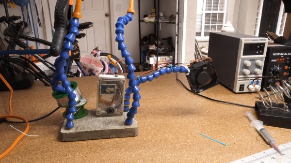
And so, in defense of his lungs, [Jeremy S Cook] added a battery-powered fume extraction fan to his custom, concrete-based solder squid. Without proper power controls, though, the fan could easily drain its battery while no actual solder activity was occurring. To tackle that problem, he recently upgraded his system with a passive infrared (PIR) sensor to control when the fan turns on and off. The PIR sensor detects motion, enabling the fan only when it sees busy hands in its view, so he no longer needs to muck around with manual controls.
Despite a large increase in functionality, the design is relatively straightforward and uses off-the-shelf components, making it an accessible project for anyone who knows their way around an iron. [Jeremy] also upgraded his power source to a LiPo battery with onboard charger, which keeps the build light, maneuverable, and easy to get close to whatever he’s working on.
An invisibility cloak may seem like science fiction, but despite that, many scientists and engineers have put much time into developing the concept, pushing it closer to reality. A device which detects the nature of its surroundings and changes its own properties to blend in may be complex, but a multitude of examples in the animal world show that it’s not impossible to achieve.
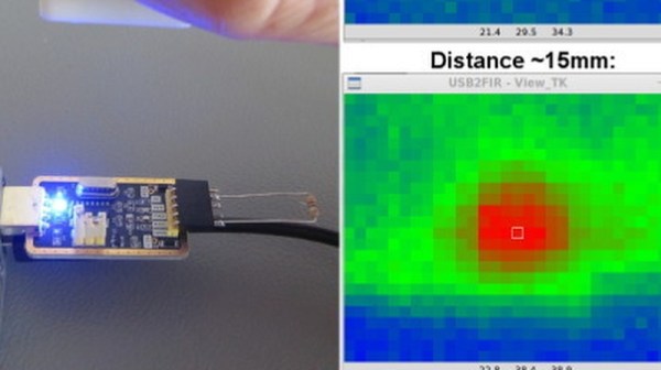
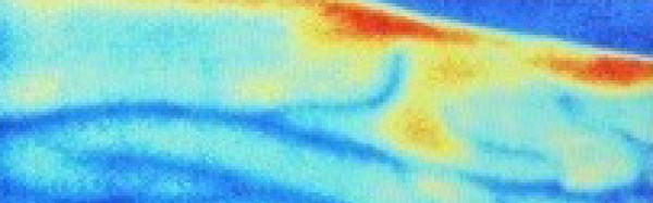
A common measurement for circuits is heat dissipation inspection. While single point thermometers do the trick, they can be quite annoying to use. Meanwhile, a thermal imaging camera is often out of the budget for hobbyists. How about building your own visual thermometer for cheap? That’s what [Thomas Fischl] decided to do, using an infrared thermal sensor array (MLX90640) connected through a PIC16LF1455 to a host computer. The computer handles the temperature calculation and visualization of hot spots, gathered from data collected by the IR pixel.
The interface board, USB2FIR, has full access to MLX90640 memory and can handle bulk transfer for faster data transmission of the raw sensor data collected by the pixel. A USB driver is needed to access the board – once the data is fetched, the visualizations can be created from a Matplotlib and TKinter GUI showing frame data and a real time heat map with minimum, maximum, and central temperature.
The hardware isn’t complicated, since the board relies on several ICs for processing the sensor data and immediately sends over the data to be processed externally. With some modifications – a 3D-printed enclosure, for instance – this can easily be made into a discreet tool for heat detection.
In the hacker and DIY community, there are people who have exceptional knowledge and fantastic tools. These people are able to do what others could only dream about, and that others can only browse eBay looking for that one tool they need to do the job. One of these such people is [John McMaster]. He is the resident expert on looking inside integrated circuits. He drops acid on a chip, and he can tell you exactly how it works on the inside.
At the hardwear.io conference, [John] shared one of his techniques for reverse-engineering intgrated circuits. He’s doing this by simply looking at the transistors, and looking at the light they give off. He’s also looking at the wrong side of the die.
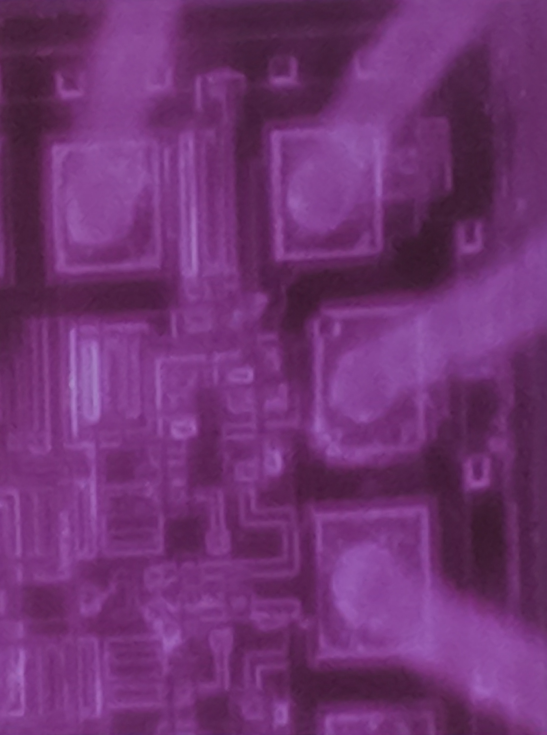
The technique [John] is using is properly called backside analysis, or looking at the infrared emissions of electron recombinations. This happens at the junction of every transistor when it’s active, and these photons are emitted at the bandgap of silicon, or about 1088 nm, far into the infrared. This sort of thing has been done before by [nedos] at CCC in 2013, but rarely have we seen a deep dive into the tools and techniques needed to look at the reverse side of an IC and see the photons coming off.
An IC, seen in infrared
There are several tools [John] used for this work, and he actually did a good comparison of different camera technologies used to image infrared photon emissions from integrated circuits. InGaAs cameras are expensive, but they offer high sensitivity. New back-illuminated CMOS cameras and cooled CCDs normally reserved for astrophotography were also tested, and as always, you get what you pay for; the most expensive cameras worked best, but there were ways you could make the cheap ones work.
As with any camera work, preparing the lighting is of utmost importance. This includes an IR pass filter, and using only LED lighting in the lab with no sunlight, incandescent, or halogen light bulbs in the room — you don’t want any IR, after all. A NIR objective in the microscope was sourced from eBay, for about 1/10th the normal cost, because the objective had a small, insignificant scratch. Using this NIR objective made the image twice as bright as any other method. You can successfully image a chip with this, and [John] tested the setup on a resistor inside a CD4050 chip; the resistor glowed a slight purple, the color you would expect with infrared sensors. But can it work with I/O levels in a more modern chip? Also, yes. It needs some Photoshop to process, and stretching the 12-bit or 16-bit color space into an 8-bit color space, but it does work.
Finally, the supreme achievement of doing backside IR analysis. Is that possible with even this minimal setup? This requires some preparation; the silicon substrate in an IC is transparent in IR, but there is attenuation and this is especially important when the substrate is 300 um thick. This needs to be shaved down to about 25 um thick, which surprisingly is best done with fine sandpaper and a finger.
While few IR emissions were observed via backside emissions, the original plan wasn’t to completely analyze the chip, but merely to do some floor planning. For this, it worked. It’s a remarkable amount of work to see the inside of a silicon chip.
While the era of the TiVo (and frankly, the idea of recording TV broadcasts) has largely come to a close, there are still dedicated users out there who aren’t quite ready to give up on the world’s best known digital video recorder. One such TiVo fanatic is [Gavan McGregor], who recently tried to put a TiVo Series 3 recorder into service, only to find the device was stuck in the family-friendly “KidZone” mode.
Without the code to get it out of this mode, and with TiVo dropping support for this particular recorder years ago, he had to hack his way back into this beloved recorder on his own. The process was made easier by the simplistic nature of the passcode system, which only uses four digits and apparently doesn’t impose any kind of penalty for incorrect entries. With only 10,000 possible combinations for the code and nothing to stop him from trying each one of them in sequence, [Gavan] just needed a way to bang them out.
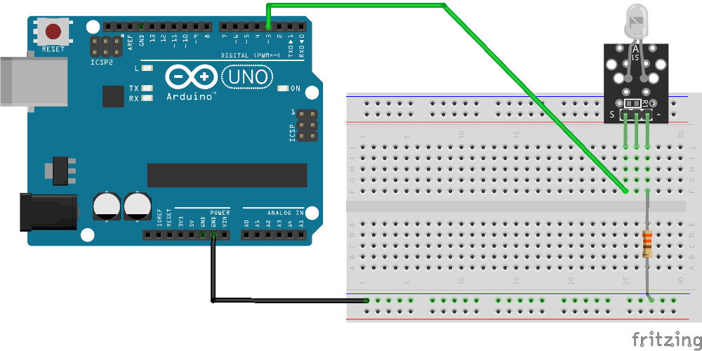
After doing some research on the TiVo remote control protocol, he came up with some code for the Arduino using the IRLib2 library that would brute force the KidZone passcode by sending the appropriate infrared codes for each digit. He fiddled around with the timing and the delay between sending each digit, and found that the most reliable speed would allow his device to run through all 10,000 combinations in around 12 hours.
The key thing to remember here is that [Gavan] didn’t actually care what the passcode was, he just needed it to be entered correctly to get the TiVo out of the KidZone mode. So he selected the “Exit KidZone” option on the TiVo’s menu, placed his Arduino a few inches away from the DVR, and walked away. When he came back the next day, the TiVo was back into its normal mode. If you actually wanted to recover the code, the easiest way (ironically) would be to record the TV as the gadget works its way through all the possible digits.
Phlebotomy is a fun word, and the fine art of finding veins. While the skill of putting needles in arms is honed by nurses and physicians over the course of decades, there are, of course, technological solutions to finding veins. One of the more impressive medical devices that does this uses near-infrared imaging — basically looking under the skin with almost visible light. These devices cost a fortune.
One project in the Hackaday Prize is looking to change that. It’s a near-infrared vein finder. Instead of the thousands of dollars professional unit costs, this one can be built for under one hundred bucks.
As far as this build goes, veins are illuminated via IR light at about 950nm. The backscatter of this light is captured via a Raspberry Pi NoIR camera, with regular old photography film blocking visible light. From there, it’s just a simple matter of image processing and hitting enhance several times until veins appear on a display.
The team behind this project has already developed a mobile version of the device, complete with 3D printed parts. It’s a handy device and a great entry for the Hackaday Prize.
We’re all used to touch pads on our laptops, and to touch screens. It’s an expectation now that a new device with a screen will be touch-enabled.
For very large surfaces though, touch is still something of an expensive luxury. If you’re a hardware hacker, unless you are lucky enough to score an exceptional cast-off, the occasional glimpse of a Microsoft PixelSense or an interactive whiteboard in a well-equipped educational establishment will be the best you’re likely to get.
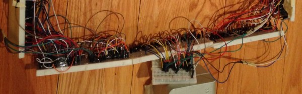
[Adellar Irankunda] may have the answer for your large touch board needs if you aren’t well-heeled, he’s made one using the interesting approach of surrounding the touch area with an array of infra-red LEDs and photo transistors. By studying the illumination of the phototransistors by different LEDs in the array, he can calculate the position of anything such as a pointing finger that enters the space. It’s an old technique that you might have found on some of the earlier touch screen CRT monitors.
His hardware is built on twelve breadboards mounted in a square, upon which sit 144 LED/phototransistor pairs managed through a pile of 4051 CMOS multiplexers by a brace of Arduino Nanos. If you fancy one yourself he’s provided all the code, though the complex array of breadboards to assemble are probably not for the faint-hearted. You can see it in action in a video we’ve posted below the break.