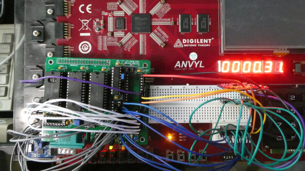
This Week In Security: Updates, Leaks, Hacking Old Hardware, And Making New

First off, Apple has issued an update for some very old devices. Well, vintage 2013, but that’s a long time in cell-phone years. Fixed are a trio of vulnerabilities, two of which are reported to be exploited in the wild. CVE-2021-30761 and CVE-2021-30762 are both flaws in Webkit, allowing for arbitrary code execution upon visiting a malicious website.

The third bug fixed is a very interesting one, CVE-2021-30737, memory corruption in the ASN.1 decoder. ASN.1 is a serialization format, used in a bunch of different crypto and telecom protocols, like the PKCS key exchange protocols. This bug was reported by [xerub], who showed off an attack against locked iPhone immediately after boot. Need to break into an old iPhone? Looks like there’s an exploit for that now. Continue reading “This Week In Security: Updates, Leaks, Hacking Old Hardware, And Making New”

Mistaken Identity — Piezo Actuators Not Test Pads

One hard disk recently failed in the EEVBlog laboratory’s NAS. Keeping true to his catch phrase, [Dave “Tear it Apart” Jones] opened it up and gave us an inside tour of a modern hard disk drive. There are so many technological wonders to behold in modern HDDs these days — the mechanical design, electronics and magnetics, and the signal processing itself which is basically an advanced RF receiver — that we can forgive [Dave] for glossing over a system of piezo actuators thinking they were manufacturing test points. Even knowing they are actuators, you have to stare at them and think for a bit before your brain accepts it.

Later realizing the mistake, he made a follow-up video (down below) focusing on just the disk head actuator arms and this micro-actuation system (or perhaps they are milli-actuators). The basic concept is a pair of piezoelectric transducers mounted on either side of the short arm holding the read head. Presumably they are driven out of phase to flex the arm left or right, but the motion is imperceptible to the eye — even under magnification, [Dave] was not able to discern any motion when he pulsed the transducers. When you consider that these micro-actuators are mounted on the main actuator arm, which itself is also in motion, the nested control loop arrangement to maintain nanometers of accuracy is truly amazing. Check out this 45 second explanatory video by Western Digital which has a good animation of the concept.

If you want to see your HDD in operation without taking it apart, check out the transparent drive we wrote about last month. And to read more about esoteric actuators, check out this article from 2015 which contains one of the longest words to appear in our pages — magnetorheological. If you’ve experience a hard disk failure, which thankfully is becoming rarer these days, do you chunk it or tear it apart?

Continue reading “Mistaken Identity — Piezo Actuators Not Test Pads”

Blowing A 5000 A Fuse Takes Some Doing

Fuses are generally there to stop excessive electrical currents from damaging equipment or people’s soft, fleshy bodies when faults occur. However, some people like to blow them just for fun, and [Photonicinduction] is just one of those people. He recently decided to push the boat out, setting his mind to the task of popping a 5000 A fuse in his own back yard. (Video, embedded below.)

The fuse looks quite haggard after the event

It’s not a job for the faint-hearted. The fuse is rated at 5,000 A — that’s the nominal rating for the currents at which it is intended to operate. Based on the datasheet, the part in question is capable of withstanding 30,000 A for up to five full seconds. To pop the fuse instantly takes something in the realm of 200,000 A.

To achieve this mighty current, a capacitor bank was built to dump a huge amount of energy through the fuse. Built out of ten individual capacitor units wired up in parallel, the total bank comes in at 10,000 μF, and is capable of delivering 200,000 A at 3000 V. (Just not for very long.) The bank was switched into circuit with the fuse via a pneumatic switch rated at just 12,000 A.

The results are ferocious, with both the fuse and switch contacts blasting out hot metal and flashes of light when the power is dumped. It’s a heck of a display. We’ve featured big capacitor banks before too, though they pale in comparison to what we’ve seen here today.

Continue reading “Blowing A 5000 A Fuse Takes Some Doing”

Scratch Built Tracked Robot Reporting For Duty

Inspired by battle-hardened military robots, [Engineering Juice] wanted to build his own remote controlled rover that could deliver live video from the front lines. But rather than use an off-the-shelf tracked robot chassis, he decided to design and 3D print the whole thing from scratch. While the final product might not be bullet proof, it certainly doesn’t seem to have any trouble traveling through sand and other rough terrain.

Certainly the most impressive aspect of this project is the roller chain track and suspension system, which consists of more than 200 individual printed parts, fasteners, bearings, and linkages. Initially, [Engineering Juice] came up with a less complex suspension system for the robot, but unfortunately it had a tendency to bind up during testing. However the new and improved design, which uses four articulated wheels on each side, provides an impressive balance between speed and off-road capability.

Internally there’s a Raspberry Pi 4 paired with an L298 dual H-bridge controller board to drive the heavy duty gear motors. While the Pi is running off of a standard USB power bank, the drive motors are supplied by a custom 18650 battery pack utilizing a 3D printed frame to protect and secure the cells. A commercial night vision camera solution that connects to the Pi’s CSI header is mounted in the front, with live video being broadcast back to the operator over WiFi.

To actually control the bot, [Engineering Juice] has come up with a Node-RED GUI that’s well suited to a smartphone’s touch screen. Of course with all the power and flexibility of the Raspberry Pi, you could come up with whatever sort of control scheme you wanted. Or perhaps even go all in and make it autonomous. It looks like there’s still plenty of space inside the robot for additional hardware and sensors, so we’re interested to see where things go from here.

Got a rover project in mind that doesn’t need the all-terrain capability offered by tracks? A couple of used “hoverboards” can easily be commandeered to create a surprisingly powerful wheeled platform to use as a base.

Continue reading “Scratch Built Tracked Robot Reporting For Duty”

The Regulatory Side Of Rolling Your Own Moderate Solar Farm

[Russell Graves] lives in Idaho and recently connected his solar installation to the grid, which meant adhering to regulatory requirements for both the National Electric Code (NEC) as well as complying with the local power company’s own regulations. His blog post is an interesting look at the whole regulatory process and experience, and is of interest to anyone curious about running their own solar farm, whether they have plans to connect it to the grid or not.

A circuit breaker that met NEC code, but not the power company’s requirements.

The power company has a very different set of priorities from the NEC, and part of [Russell]’s experience was in having to meet requirements that weren’t documented in the expected places, so study of the materials didn’t cut it. In particular, the power company needed the system to have disconnects with conductors that visually move out of position when disconnected. [Russell] was using NEC-compliant circuit breakers that met NEC code, but they didn’t meet the power company requirement for conductors that can be visually confirmed as being physically disconnected. Facing a deadline, [Russell] managed to finesse a compliant system that was approved, and everything got signed off just as winter hit.

How well does his solar farm work out? Sometimes the panels produce a lot of power, sometimes nearly nothing, but it has been up and running for all of winter and into spring. Over the winter, [Russell] pulled a total of 3.1 MWh from the grid, mainly because his home is heated with electric power. But once spring hit, he started pushing considerably more into the grid than he was pulling; on some days his setup produces around 95 kWh, of which about 70 kWh gets exported.

[Russell] didn’t go straight to setting up his own modest solar farm; we saw how he began by making his own ideal of a perfect off-grid office shed that ran on solar power, but it has certainly evolved since then and we’re delighted to see that he’s been documenting every bit of the journey.

Using Heaters To Display Time

We’re always fans of interesting clock builds around here, whether it’s a word clock, marble clock, or in this case a clock using a unique display method. Of course, since this is a build by Hackaday’s own [Moritz v. Sivers] the display that was chosen for this build was a custom thermochromic display. These displays use heat-sensitive material to change color, and his latest build leverages that into one of the more colorful clock builds we’ve seen.

The clock’s display is built around a piece of thermochromic film encased in clear acrylic. The way the film operates is based on an LCD display, but using heat to display the segments. For this build, as opposed to his previous builds using larger displays, he needed to refine the method he used for generating the heat required for the color change. For that he swapped out the Peltier devices for surface mount resistors and completely redesigned the drivers and the PCBs around this new method.

Of course, the actual clock mechanism is worth a mention as well. The device uses an ESP8266 board to handle the operation of the clock, and it is able to use its wireless capabilities to get the current time via NTP. All of the files needed to recreate this are available on the project page as well, including code, CAD files, and PCB layouts. It’s always good to have an interesting clock around your home, but if you’re not a fan of electronic clocks like this we can recommend any number of mechanical clocks as well.

Continue reading “Using Heaters To Display Time”

Upgrading The PowerBook 100 With A Fresh New Battery

The PowerBook 100 was one of the earliest Apple laptops released, coming not long after the breakout Macintosh Portable. Unlike modern hardware, it relied on sealed lead acid batteries. [360alaska] has such a laptop whose original battery is long dead, so they set about building a replacement battery with lithium cells instead.

The battery and its associated support circuitry is a mite unconventional in its design, but it gets the job done. The build uses two lithium polymer pouch cells in place of the original four cell sealed-lead acid battery, to replicate the roughly 7.2V nominal voltage. Because of this, unfortunately the stock PowerBook charger can’t provide enough voltage to fully charge the LiPo cells up to their full 8.4 volts.

The workaround selected is that when the batteries fall below 80% state of charge, relays disconnect the cells from their series configuration powering the laptop, and instead connect each cell to its own single-cell charger board. Once charging is complete, the relays switch back out of charging mode so the batteries power the laptop once more. The only major drawback is that withdrawing the power adapter while the batteries are on charge will cut all power to the laptop.

It may not be perfect, but [360alaska] has succeeded in building a drop-in battery solution for the PowerBook 100 that can be used with the stock charger. Laptop batteries can be a fraught thing to deal with; often there are safeguards or DRM-type issues to navigate to get them to work around. Sometimes open-source designs are the best solution out there.