Logic Noise: Ping-pong Stereo, Mixers, And More

So far on Logic Noise, we’ve built up a bunch of sound-making voices and played around with sequencing them. The few times that we’ve combined voices together, we’ve done so using the simplest possible passive mixer — a bunch of resistors. And while that can work, we’ve mostly just gotten lucky. In this session, we’ll take our system’s output a little bit more seriously and build up an active mixer and simple stereo headphone driver circuit.

For this, we’ll need some kind of amplification, and our old friend, the 4069UB, will be doing all of the heavy lifting. Honestly, this week’s circuitry is just an elaboration of the buffer amplifiers and variable overdrive circuits we looked at before. To keep things interesting we’ll explore ping-pong stereo effects, and eventually (of course) put the panning under logic-level control, which is ridiculous and mostly a pretext to introduce another useful switch IC, the 4066 quad switch.

At the very end of the article is a parts list for essentially everything we’ve done so far. If you’ve been following along and just want to make a one-time order from an electronics supply house, check it out.

klangorium
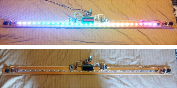
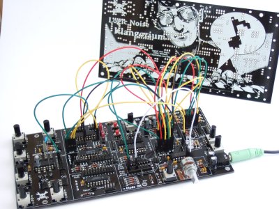
If you’re wondering why the delay in putting out this issue of Logic Noise, it’s partly because I’ve built up a PCB that incorporates essentially everything we’ve done so far into a powerhouse of a quasi-modular Logic Noise demo — The Klangorium. The idea was to take the material from each Logic Noise column so far and build out the board that makes experimenting with each one easy.

Everything’s open and documented, and it’s essentially modular so you can feel free to take as much or as little out of the project as you’d like. Maybe you’d like to hard-wire the cymbal circuit, or maybe you’d like to swap some of the parts around. Copy ours or build your own. If you do, let us know!

OK, enough intro babble, let’s dig in.

Continue reading “Logic Noise: Ping-pong Stereo, Mixers, And More”

LED Strip Pong As An Arduino Shield

led-pong-strip

[Schuyler Sowa] has been hard at work on his own version of LED strip Pong. We’d say his work has really paid off. The game is robust and full of features.

Unlike the original Pong video game LED pong only has one axis on which the ball travels. The ball will bounce back if the button at the end of the strip is pressed when either of the last two LED pixels are illuminated. To add in a difficulty adjustment [Schuyler] included a poteniometer which alters the speed.

The game board is one meter of LED strip with individually addressable pixels. It cost a whopping $28 and was the second kind he tried after having trouble with the WS2801 based version (which often come as strings of lights). An Arduino board controls the game, with a shield made from protoboard to connect the components. In addition to the two user buttons — which were hacked out of a computer keyboard — you’ll notice a pair of seven segment displays acting as a scoreboard and an HD44780 character LCD rounding out the user interface.

Continue reading “LED Strip Pong As An Arduino Shield”

Perpetual Pong

perpetual-pong

[Jeff Joray] wrote in to show off this perpetual Pong device he built. The six by ten LED matrix acts as a game board for Pong but there are no controls. The board simply plays against itself. It’s pretty much a pong clock without the clock.

The brain of the device is a PIC 16F684 which drives the six rows of the display directly. He went with a decade counter (CD74HC401) to scan the rows one at a time. Now what would you expect to find on the underside of this hunk of protoboard? A rat’s nest of point to point wiring? If so you’re going to be disappointed. [Jeff] spent the time to generate a schematic and board layout in Eagle. While at it, he knew he was going to be using protoboard so the artwork is designed to use solder bridging as much as possible. What he ends up with is one of the cleanest mutiplexed one-off projects you’re going to find. See it in action after the jump.

Continue reading “Perpetual Pong”

MonoPong: A CMOS 1-D Pong

We’ve seen a few 1-D pong games recently, and they’ve all be controlled using microcontrollers. Inspired by some of these hacks, [mischka] built the monoPong using a handful of logic chips.

The monoPong has four major components. A 555 timer in astable mode provides a clock source which is fed into a 4510 decade counter, which connects to a 4028 BCD to decimal decoder to drive the LEDs. Finally, a 4011 NAND gate IC is used to deal with the button presses. Two of the NAND gates form a RS flip-flop, and the other two NAND each player’s button with the last LED on the player’s side of the strip. If the player hits the button when their LED is on, the RS flip-flop toggles and changes the decade counter from count up to count down mode. This makes the ball bounce back.

[mischka] finished the project off by putting it in a wooden box and drilling holes for the LEDs, buttons, and a power switch. The final product looks pretty good, and is a great example of how you can use a couple logic chips instead of a microcontroller.

After the break, watch a quick game of monoPong.

Continue reading “MonoPong: A CMOS 1-D Pong”

One Dimensional PONG Is A Great Use For LED Strips

[Jason] has had a five meter addressable RGB LED strip lying around for a while, and only recently came up with a good idea of what to use it for. He came up with One Dimensional PONG, and it looks like it’s a blast to play. Instead of moving a paddle up and down, [Jason]’s 1D PONG game requires the players to stomp on a switch to send the ball back to the other player.

The LED strip [Jason] used has an SPI interface, but needed to be PWM clocked to a microcontroller to operate. After whipping up an Arduino library for his LED strip, [Jason] built an ATMega328-based controller board and a pair of seven segment display boards to keep track of the score. There’s a technical overview in another one of [Jason]’s videos.

[Jason] will be taking his 1D PONG game to the Brighton Mini Maker Faire on September 8th. We’re sure his game will be very popular there, so if you see him, tell him Hackaday sent you.

Continue reading “One Dimensional PONG Is A Great Use For LED Strips”

Automatic Daylight Saving Time Compensation For Your Clock Projects

Pretty early in development of my Ping Pong Clock I came up with the idea of automatic Daylight Saving Time compensation. It’s an interesting feature, but it’s a luxury and so I figured I could add it as a future improvement. Now’s the time and I’m reporting back on what I’ve learned and how you can add this to your own projects.

There’s two things to think about before adding this feature. Is it worth the effort and does it make the clock more confusing rather than easier to use?

As to the latter, if you are responsible for setting the time initially but you are not responsible for resetting the clock when we fall back or spring forward will it cause confusion? Perhaps initially, but the battery-backed RTC that I used in my project should mean that you set it once and never have to reset it again. The one exception is DST and that’s what I’m compensating for.

Whether it is worth it or not is difficult to answer until after the fact. You should take into consideration that the DST rules are not set in stone, they change from time to time. Add to that the fact that not all parts of the world observe the practice. This means that not only do you need to implement the compensation, but you should add a method of switching it on and off as well as changing the rules for when it is observed.

Join me after the break to learn the method and code I use to make time adjustments automatically twice a year.

Continue reading “Automatic Daylight Saving Time Compensation For Your Clock Projects”

Oscilloscope Clock Made Possible By Dumpster Diving

We see people driving around the night before trash collection and reclaiming items doomed to the land fill (or on their way to recycling… who knows). We’re beginning to think we need to join those ranks. Case in point is this vintage oscilloscope which [Bob Alexander] plucked from the curb in the nick of time. Here’s the kicker, when he got it home he found it still worked! He couldn’t let this opportunity go to waste, so he figured out how to turn it into a clock without losing the ability to use it as a scope.

You probably already know that it’s possible to display your own graphics on an oscilloscope. In fact, you can buy a board from Sparkfun which will turn the scope into an analog clock, and that’s exactly what [Bob] did. But he was met with two problems, the X-axis was flipped and he didn’t have an easy way to power the board.

He struggled with the voltage supply, frying his first attempt at boosting the internal 6.3V supply to use with a linear 5V regulator. His second attempt worked though, soldering a 12V regulator to the transformer. He was then on to the X-axis correction, using a rail-to-rail op-amp to invert the signal. The project finishes by adding toggle controls and buttons on the back of the case to switch between scope and clock modes, and to set the time.