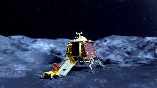
On July 22nd, India launched an ambitious mission to simultaneously deliver an orbiter, lander, and rover to the Moon. Launched from the Satish Dhawan Space Centre on a domestically-built GSLV Mk III rocket, Chandrayaan-2 is expected to enter lunar orbit on August 20th. If everything goes well, the mission’s lander module will touch down on September 7th.
Attempting a multifaceted mission of this nature is a bold move, but the Indian Space Research Organisation (ISRO) does have the benefit of experience. The Chandrayaan-1 mission, launched in 2008, spent nearly a year operating in lunar orbit. That mission also included the so-called Moon Impact Probe (MIP), which deliberately crashed into the surface near the Shackleton crater. The MIP wasn’t designed to survive the impact, but it still secured India a position on the short list of countries that have placed an object on the lunar surface.
If the lander component of Chandrayaan-2, named Vikram after Indian space pioneer Vikram Sarabhai, can safely touch down on the lunar surface it will be a historic accomplishment for the ISRO. To date, the only countries to perform a controlled landing on the Moon are the Soviet Union, the United States, and China. Earlier in the year, it seemed Israel would secure its position as the fourth country to perform the feat with their Beresheet spacecraft, but a last second fault caused the craft to crash into the surface. The loss of Beresheet, while unfortunate, has given India an unexpected chance to take the coveted fourth position despite Israel’s head start.
We have a few months before the big event, but so far, everything has gone according to plan for Chandrayaan-2. As we await word that the spacecraft has successfully entered orbit around the Moon, let’s take a closer look at how this ambitious mission is supposed to work.


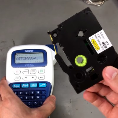 At first, the printer didn’t even want to recognize the cassette. It seems like Brother doesn’t want you using exotic tapes with cheap printers. No worry, this isn’t sophisticated DRM, just a sense hole that you need to cover with tape. This discovery was made using the extremely scientific trick of covering all the holes that were not on a regular cassette.