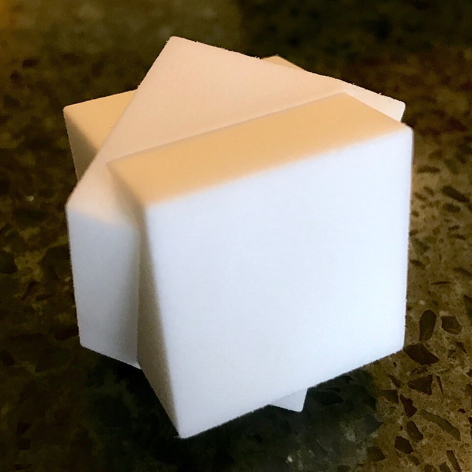
Can a shape pass through itself? That is to say, if one had two identical solids, would it be possible to orient one such that a hole could be cut through it, allowing the other to pass through without breaking the first into separate pieces? It turns out that the answer is yes, at least for certain shapes. Recently, two friends, [Sergey Yurkevich] and [Jakob Steininger], found the first shape proven not to have this property.
A 3D-printed representation of a cube passing through itself [image: Wikipedia]Back in the late 1600s, Prince Rupert of the Rhine proved it was possible to accomplish this feat with two identical cubes. One can tilt a cube just so, and the other cube can fit through a tunnel bored through it. A representation is shown here.
Later, researchers showed this was also true of more complex shapes. This ability to pass unbroken through a copy of oneself became known as Rupert’s Property. Sometimes it’s an amazingly tight fit, but it seems to always work.
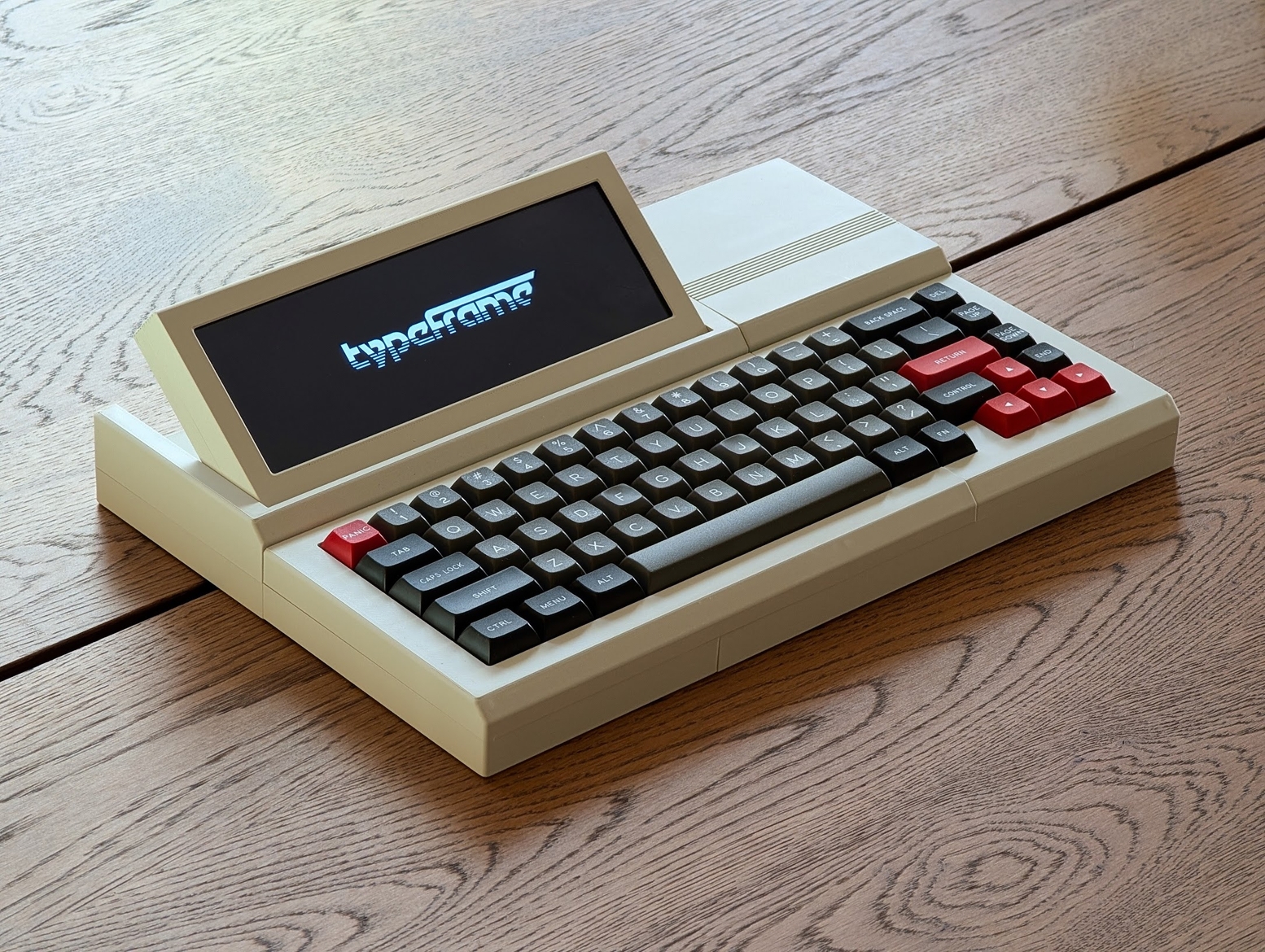
I must confess that my mouth froze in an O when I saw [Jeff]’s Typeframe PX-88 Portable Computing System, and I continue to stare in slack-jawed wonder as I find the words to share it with you. Let me give it a shot.
[Jeff] tells us that he designed Typeframe for his spouse to use as a writer deck. That’s good spousing, if you ask me. Amazingly, this is [Jeff]’s first project of this type and scope, and somehow it’s an elegant, yet easy build that’s quite well documented to boot. Whatever Typeframe’s design may borrow, it seems to give back in spades.
Image by [Jeff] via Typeframe.netUse Typeframe for what you will — cyberdeck, writer deck, travel PC — this baby can handle whatever you throw at it. And of course, it’s open source from front to back.
This Raspberry Pi 4B-based productivity machine has all sorts of neat features. The touch screen flips upward at an angle, so you don’t have to hunch over it or carry a mouse around. Want to sit back a bit while you work? The aesthetically spot-on keyboard is detachable. Yeah.
If that’s not enough to get you interested, Typeframe is designed for simple construction with minimal soldering, and the sliding panels make maintenance a breeze.
A little more about that keyboard — this is Keebin’, after all. It’s an MK Point 65, which boasts hot-swap sockets under those DSA Dolch keycaps. See? Minimal soldering. In fact, the only things you have to solder to make the Typeframe your own are the power switch and the status light. Incredible.
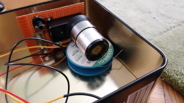
Among the many science toys that have fallen out of fashion since we started getting nervous around things like mercury, chlorinated hydrocarbons, and radiation is the spinthariscope, which let people watch the flashes of light on a phosphor screen as a radioactive material decayed behind it. In fact, they hardly expose their viewers to any radiation, which makes [stoppi]’s homemade spinthariscope much safer than it might first seem.
[Stoppi] built the spinthariscope out of the eyepiece of a telescope, a silver-doped zinc sulfide phosphor screen, and the americium-241 capsule from a smoke detector. A bit of epoxy holds the phosphor screen in the lens’s focal plane, and the americium capsule is mounted on a light filter and screwed onto the eyepiece. Since americium is mainly an alpha emitter, almost all of the radiation is contained within the device.
After sitting in a dark room for a few minutes to let one’s eyes adjust, it’s possible to see small flashes of light as alpha particles hit the phosphor screen. The flashes were too faint for a smartphone camera to pick up, so [stoppi] mounted it in a light-tight metal box with a photomultiplier and viewed the signal on an oscilloscope, which revealed many small pulses.
Today, if you can find a pneumatic tube system at all, it is likely at a bank drive-through. A conversation in the Hackaday bunker revealed something a bit surprising. Apparently, in some parts of the United States, these have totally disappeared. In other areas, they are not as prevalent as they once were, but are still hanging in there. If you haven’t seen one, the idea is simple: you put things like money or documents into a capsule, put the capsule in a tube, and push a button. Compressed air shoots the capsule to the other end of the tube, where someone can reverse the process to send you something back.
These used to be a common sight in large offices and department stores that needed to send original documents around, and you still see them in some other odd places, like hospitals or pharmacy drive-throughs, where they may move drugs or lab samples, as well as documents. In Munich, for example, a hospital has a system with 200 stations and 1,300 capsules, also known as carriers. Another medical center in Rotterdam moves 400 carriers an hour through a 16-kilometer network of tubes. However, most systems are much smaller, but they still work on the same principle.
[Usagi Electric] is known for minicomputers, but in a recent video, he shows off his TMS9900-based homebrew computer. The TMS9900 CPU was an early 16-bit CPU famously used in the old TI-99/4A computer, but as the video points out, it wasn’t put to particularly good use in the TI-99/4A because its RAM was hidden behind an inefficient interface and it didn’t leverage its 16-bit address space.
The plan is for this computer to have 2K words of ROM, 6K words of RAM, and three serial lines: one for the console terminal, another for a second user console terminal, and the third for access to a tape drive.
The infrared transceiver installed on the washing machine. (Credit: Severin)
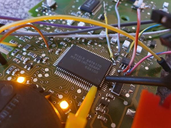
Since modern household appliances now have an MCU inside, they often have a diagnostic interface and — sometimes — more. Case in point: Miele washing machines, like the one that [Severin] recently fixed, leading to the firmware becoming unhappy and refusing to work. This fortunately turned out to be recoverable by clearing the MCU’s fault memory, but if you’re unlucky, you will have to recalibrate the machine, which requires very special and proprietary software.
Naturally, this led [Severin] down the path of investigating how exactly the Miele Diagnostic Utility (MDU) and the Program Correction (PC) interface communicate. Interestingly, the PC interface uses an infrared LED/receiver combination that’s often combined with a status LED, as indicated by a ‘PC’ symbol. This interface uses the well-known IrDA standard, but [Severin] still had to track down the serial protocol.
[Thinking Techie] takes us back to basics in a recent video explaining how magnets, coils, brushed DC motors, and brushless DC motors work. If this is on your “to learn” list, or you just want a refresher, you can watch the video below. It’ll be ten minutes well-spent.
The video covers the whole technology stack behind the humble DC motor in its various incarnations. Starting with basic magnetic effects, it then proceeds through 2-wire brushed DC motors and finally into 3-wire brushless DC motors (BLDC motors).


![[Usagi Electric] and his home brew computer](https://hackaday.com/wp-content/uploads/2025/11/TMS9900-home-brew-banner.jpg?w=600&h=450)