
They might call it Levity, but there’s nothing funny about Rapid Liquid Print’s new silicone 3D printer. It has to be seen to be believed, and luckily [3D Printing Nerd] gives us lots of beauty shots in this short video, embedded below.
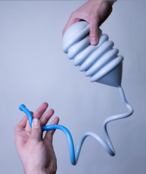
Printing a liquid, even a somewhat-viscous one like platinum-cure silicone, presents certain obvious challenges. The Levity solves them with buoyancy: the prints are deposited not onto a bed, but into a gel, meaning they are fully supported as the silicone cures. The fact that the liquid doesn’t cure instantly has a side benefit: the layers bleed into one another, which means this technique should (in theory) be stronger in all directions than FDM printing. We have no data to back that up, but what you can see for yourself that the layer-blending creates a very smooth appearance in the finished prints.
If you watch the video, it really looks like magic, the way prints appear in the gel. The gel is apparently a commercially-available hydrogel, which is good since the build volume looks to need ̶a̶b̶o̶u̶t̶ ̶5̶0̶0̶ ̶L̶ at least 125 L of the stuff. The two-part silicone is also industry-standard and off-the-shelf, though no doubt the exact ratios and are tweaked for purpose. There’s no magic, just a really neat technology.
If you want one, you can sign up for the waiting list at Rapid Liquid Print’s website, but be prepared to wait; units ship next year, and there’s already a list.
Alternatively, since there is no magic here, we’d love to see someone take it on themselves, the way once equally exotic SLS printers have entered the DIY world. There was a time when resin printers were new and exotic and hobbyists had to roll their own, too. None of this is to say we don’t respect the dickens out of the Rapid Liquid Print team and their achievement–it’s just that imitation is the sincerest form of flattery. Continue reading “Liquid Silicone 3D Printing Is No Joke”


 This levitator is USB-powered, and typically draws 1 W to 3 W to levitate masses between 10 g and 500 g. The base can provide 3 V to 5 V inductive power to the levitator to the tune of 10 mA to 50 mA, which is enough for some interesting possibilities, starting with the lights and motors [Jonathan] has tried.


