Decoding A ROM From A Picture Of The Chip

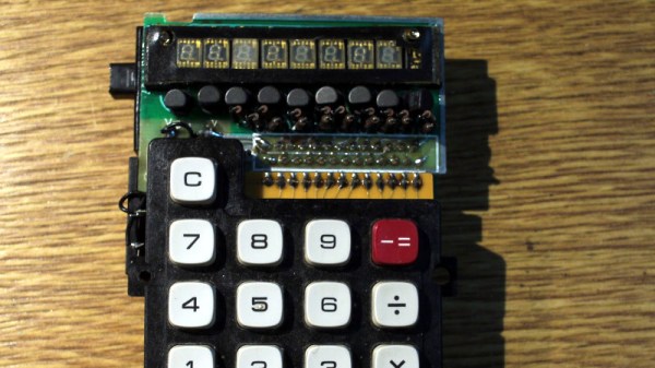
Before there were home computers, among the hottest pieces of consumer technology to own was a pocket calculator. In the early 1970s a series of exciting new chips appeared which allowed the impossible to become the affordable, and suddenly anyone with a bit of cash could have one.

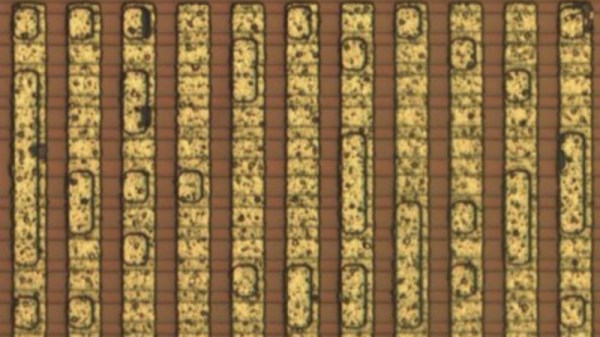
Perhaps one of the more common series of chips came from Texas instruments, and it’s one of these from which [Veniamin Ilmer] has retrieved the ROM contents. In a way there’s nothing new here as the code is well known, it’s the way it was done which is of interest. A photo of the die was analysed, and with a bit of detective work the code could be deduced merely from the picture.

These chips were dedicated calculators, but under the hood they were simple pre-programmed microcontrollers. Identifying the ROM area of the chip was thus relatively straightforward, but some more detective work lay in getting to the bottom of how it could be decoded before the code could be verified. So yes, it’s possible to read code from an early 1970s chip by looking at a photograph.

A very similar chip to this one was famously reprogrammed with scientific functions to form the heart of the inexpensive Sinclair Cambridge Scientific.

Make Your Own 1970s Magnetic Stripe Cards

We’re now all used to near-limitless storage on flash and other semiconductor technologies, but there was a time when persistent storage was considerably less easy to achieve. A 1970s programmable calculator from Sharp approached the problem with magnetic strips on special cards, and since [Menadue] has one with no cards, he set about making his own.

These cards are a little different to the credit-card-style cards we might expect, instead they’re a narrow strip with a magnetic stripe down their centre. The unusual feature can be found at the edge, where a row of perforations provide the equivalent of a clock line.

The newly manufactured cards have the clock slots machined along their edges, and then the magnetic part formed from self-adhesive magnetic strip. This last thing is a product we were not aware existed, and can think of plenty of possible applications.

The result as you can see in the video below the break are some cards with variable reliability. There’s a suggestion that white cards might work less well with the infrared light used in the clock detector, also a suspicion the low batteries make reading less easy, but still he’s able to retrieve a stored program. An extinct medium is revived.

Longtime readers will know we’ve spent time in calculator country before.

Continue reading “Make Your Own 1970s Magnetic Stripe Cards”

A Reverse Polish Calculator For Your Keychain

As the smartphone has eaten ever more of the gatgets with which we once surrounded ourselves, it’s with some sadness that we note the calculator becoming a less common sight. It’s with pleasure then that we bring you [Nekopla]’s keychain calculator, not least because it’s a little more than a conventional model. This is a calculator which uses Reverse Polish Notation, or RPN.

A full write-up in Japanese (Google Translate link) carries an impressive level of detail about the project, but in short, it takes an Arduino Pro Micro, an array of keys, and an OLED display, and packages them on a couple of fiberglass prototyping boards in a sandwich between laser-cut Perspex front and rear panels.

The RPN notation is what makes it especially interesting,a system in which where you might be used to writing 2+2=  to get 4, in RPN you would write 2 2 + . It allows the use of much simpler code with a stack-based architecture than that used in a conventional calculator. It’s a system that’s usually the preserve of some pretty exclusive machines, so it’s great to see on something with more of the toy about it.

If RPN interests you, then you might like to read our look at the subject, and even feast your eyes on the teardown of a vintage 1975 Sinclair RPN calculator.

Arduino Nano Powers Reverse Polish Notation Calculator

There’s something about Reverse Polish Notation (RPN) and the calculators that use it. It calls to mind a time when a calculator was a serious tool, and not just a throwaway toy. Created in the legacy of such calculators by HP and Texas Instruments, [Simon Boak] shows off his SB116, sporting an Arduino Nano under the hood. It’s a fully custom design, with a hand-built metal case, a custom PCB for the keyboard, and a tiny OLED display for maximum retro green goodness.

The impetus for this build was to replace a particular calculator, a well-used TI Programmer, that’s useful for working with 6502 assembly. The SB116 supports binary, octal, decimal, and hex; and boasts some downright useful functions — AND, NOT, OR, XOR, and bitshifts. The source code is available, but you’re on your own for the case and keyboard. And for maximized retro faux-nostalgia, [Simon] designed a box that would have looked right at home on an 80s store shelf.

Stick around for more retro-modern takes on calculators, or tales of repairing a genuine vintage model.

An HP15-C emulator PCB

Calculate Like It’s 1989 With This HP15C Emulator

Back in the day, your choice of calculator said a lot about your chops, and nothing made a stronger statement than the legendary Hewlett-Packard Voyager series of programmable calculators. From the landscape layout to the cryptic keycaps to the Reverse Polish Notation, everything about these calculators spoke to a seriousness of purpose.

Sadly, these calculators are hard to come by at any price these days. So if you covet their unique look and feel, your best bet might be to do like [alxgarza] and build your own Voyager-series emulator. This particular build emulates the HP15C and runs on an ATMega328. Purists may object to the 192×64 LCD matrix display rather than the ten-digit seven-segment display of the original, but we don’t mind the update at all. The PCB that the emulator is built on is just about the right size, and the keyboard is built up from discrete switches that are as satisfyingly clicky as the originals. We also appreciate the use of nothing but through-hole components — it seems suitably retro. The video below shows that the calculator is perfectly usable without a case; a 3D-printed case is available, though, as is an overlay that replicates the keypad of the original.

We’ve seen emulators for other classic calculators of yore, including Sinclair, Texas Instruments, and even other HP lines. But this one has a really nice design that gets us going.

Continue reading “Calculate Like It’s 1989 With This HP15C Emulator”

1973: When Calculators Were Built Like Computers

Should you ever pick up [Steve Wozniak]’s autobiography, you will learn that in the early 1970s when his friend [Steve Jobs] was working for Atari, [Woz] was designing calculators for Hewlett Packard. It seems scarcely believable today, but he describes his excitement at the prospects for the calculator business, admitting that he almost missed out on the emerging microcomputer scene that would make him famous. Calculators in the very early 1970s were genuinely exciting, and were expensive and desirable consumer items.

[Amen] has a calculator from that period, a Prinztronic Micro, and he’s subjected it to an interesting teardown. Inside he finds an unusual modular design, with keyboard, processor, and display all having their own PCBs. Construction is typical of the period, with all through hole components, and PCBs that look hand laid rather than made using a CAD package. The chipset is a Toshiba one, with three devices covering logic, display driver and clock.

The Prinztronic is an interesting device in itself, being a rebadged 1972 Sharp model under a house brand name for the British retailer Dixons, and that Toshiba chipset is special because it is the first CMOS design to market. It was one of many very similar basic calculators on the market at the time, but at the equivalent of over 100 dollars in today’s money it would still have been a significant purchase.

Long-tern Hackaday readers will remember we’ve shown you at least one classic calculator rebuild in the past, the venerable 1975 Sinclair!

A Switching Power Supply, 1940s-Style

“They don’t build ’em like they used to.” There’s plenty of truth to that old saw, especially when a switch-mode power supply from the 1940s still works with its original parts. But when said power supply is about the size of a smallish toddler and twice as heavy, building them like the old days isn’t everything it’s cracked up to be.

The power supply that [Ken Shirriff] dives into comes from an ongoing restoration of a vintage teletype we covered recently. In that post we noted the “mysterious blue glow” of the tubes in the power supply, which [Ken] decided to look into further. The tubes are Thyratrons, which can’t really be classified as vacuum tubes since they’re filled with various gasses. Thyratrons are tubes that use ionized gas – mercury vapor in this case – to conduct large currents. In this circuit, the Thyratrons are used as half-wave rectifiers that can be rapidly switched on and off by a feedback circuit. That keeps the output voltage fixed at the nominal 140V DC required by the teletype, with a surprisingly small amount of ripple. The video below is from a series on the entire restoration; this one is cued to where the power supply is powered up for the first time. It’s interesting to see the Thyratrons being switched at about 120 Hz when the supply is under load.

Cheers to [Ken] and his retrocomputing colleagues for keeping the old iron running. Whether the target of his ministrations is a 1974 scientific calculator or core memory from an IBM 1401, we always enjoy watching him work.

Continue reading “A Switching Power Supply, 1940s-Style”