Puzzle Box

Puzzle Box Is Rigged To Blow

[Sande24] needed a gift for his father’s birthday. He decided that rather than simply give his father the gifts, he would present his father with a unique challenge. The gifts are locked inside of a multi-stage puzzle box. This isn’t your average puzzle box though. This one is rigged to blow.

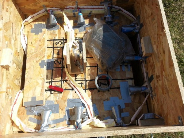
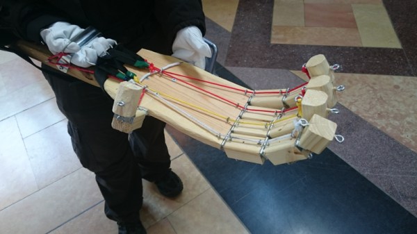
The puzzle box was designed to test his father’s reflexes, mind, and luck. The finished product looks sort of like a wooden crate made from particle board. The box contains three levels, each with its own gift and its own task to be completed.

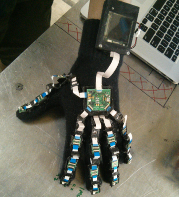
With the lid opened, the first compartment and puzzle is revealed. Inside of the compartment were a new pair of gloves, meant to protect the father’s hands when working on the puzzles. The first puzzle is built into a sheet of wood with several custom-made levers. The levers must be moved into position in order to remove the wooden sheet and reveal the next level.

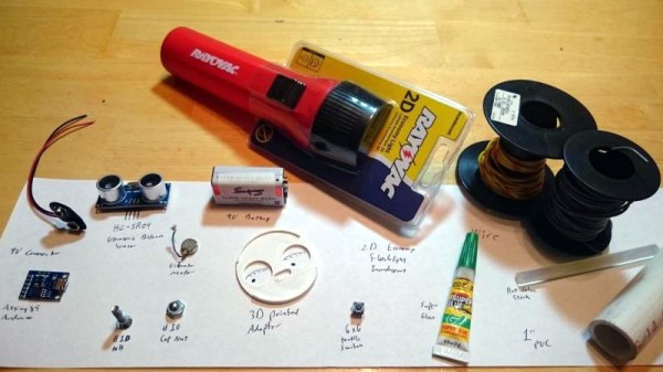
The first lever triggers a home-made detonator that eventually lights a series of fireworks placed around the box. You need to solve the puzzle box fast enough to prevent the fireworks from destroying the gifts that lay inside. [Sande24] was unable to legally purchase fuses where he lived, so he had to make his own.

The second level held a gas mask, also meant to protect the father from the booby traps of this mysterious box. This level, also made from a sheet of wood, has nine squares drawn on it. Each square is labeled with a different number which goes into solving a mathematical function (x^5-25x^4+233x^3-995x^2+1866x-1080 = 0). The solution to the function would reveal the safe path to be used to cut the wooden platform in half. Unfortunately [Sande24’s] father cut the wrong squares and released a huge amount of vinegar into the box. Oops.

The bottom level contained the final puzzle and the locked treasure compartment locked with an ordinary padlock. To find the key, another puzzle had to be solved based on a series of wooden levers labeled with different shapes. The shapes provided clues to the order in which the levers should be pulled. Once the levers were moved into position, two compartments were unlocked. One of them contained the key to the treasure box. The other contained another booby trap which would set off more fireworks, destroying the final gift of four cans of Kuld beer. That’s a lot of work to get a a few cans of frothy beverage!

[Thanks Ellery]

Hacklet 54 – Virtual Reality Projects

Virtual Reality is finally coming of age. Hackers, Makers and Engineers have dreamed of creating immersive interfaces for years. From the first flight simulators to today’s cellphone powered head mounted displays, VR has always been an exciting field. Many of the advances today are being created by hackers who were inspired by systems like Virtuality from the early 1990’s. Now 25 years on, we’re seeing amazing advances – not only in commercial systems, but in open source VR projects. This week’s Hacklet is all about the best VR projects on Hackaday.io!

vr1We start with [j0nno] and D.I.Y Virtual Reality. [J0nno] has become interested in VR, and decided to build his own head mounted display. His goal is to create a setup with full head tracking and an open source software stack. He’s hoping to do this within a budget of just $200 AUD. [J0nno] started with the Ritech3d-V2 VR Goggles, which are a plastic implementation of Google’s project cardboard. For display he’s using a 5.6 inch 1280 x 800 TFT LCD. Tracking is optical, using IR LEDs and a PS3 Eye camera. [J0nno’s] background is in software, so he’s doing great setting up OpenVR and Perception. The hardware side is a bit new to him. This isn’t stopping [J0nno] though! In true hacker spirit, he’s learning all about resistors and driving LEDs as he works on D.I.Y Virtual Reality.

vr2Next up is [Josh Lindsay] with Digitabulum: The last motion-capture glove. Digitabulum is a motion capture glove designed to be able to emulate most other motion capture systems. It is also designed to be relatively low-cost. At $400 per hand, it is less expensive than most other offerings, though we’d still love to see something even cheaper. [Josh] is going with inertial sensors, and a lot of them. Specifically he’s using no less than 17 LSM9DS1 Inertial Measurement Unit (IMU) sensors from ST Microelectronics. IMU sensors like this combine multiple rate gyros, accelerometers, and magnetometers into a single unit. Essentially every segment of every finger has its own sensor suite. As you might imagine, that is quite a bit of data to crunch. An Altera Max II CPLD and an ST Arm processor help boil down the data to something which a VR engine can process. [Josh] has been working on this project for over a year now, and he’s making great progress. The prototype glove looks terrific!

vr3[Thomas] brings augmented reality to the table with Oculus Rift featured Crane control. What started as a hobby experiment became [Thomas’] major project at university. He’s connected an Oculus Rift to a toy crane. A stereo camera on the crane sends a video image to the operator. The camera is mounted on a pan/tilt mechanism driven by the Rift’s head tracking unit. Simple joystick controls allow [Thomas] to move the boom and lower the line. On-screen displays show the current status of the crane. The use of the Rift makes this an immersive demonstration. One could easily see how moving this system into the real world would make crane operations safer for crane operators.

vr4Finally we have [Arcadia Labs] with DIY Augmented Reality Device. This project, which is the [Arcadia Labs] entry in the 2015 Hackaday Prize, uses two 320 x 240 screens to create an augmented reality head mounted display. While the resolution can’t match that of the Oculus Rift or HTC Vive, [Arcadia Labs] is ok with that. They’re going for a lower cost open source alternative for augmented reality. Tracking is achieved with an IMU, while a PS3 Eye camera provides the video. A Raspberry Pi controls the show. [Arcadia Labs] was able to get 50 frames per second on the displays just using the Pi’s SPI interface, however the USB PS3 Eye camera limits things to around 10 FPS. This project is under heavy development right now, so follow along with us to see where [Arcadia Labs] ends up!

If you want VR goodness, check out our new virtual reality projects list! Did I miss your project? Don’t be shy, just drop me a message on Hackaday.io. If you’re on the left coast of the USA, check out SOCAL Virtual Reality Conference and Expo. Hackaday is a sponsor. The event happens on July 12 at the University of California Irvine.

That’s it for this week’s Hacklet, As always, see you next week. Same hack time, same hack channel, bringing you the best of Hackaday.io!

Vibrating Distance Torch Illuminates The Dark Without Light

If you’ve ever had to move around in a dark room before, you know how frustrating it can be. This is especially true if you are in an unfamiliar place. [Brian] has attempted to help solve this problem by building a vibrating distance sensor that is intuitive to use.

The main circuit is rather simple. An Arduino is hooked up to both an ultrasonic distance sensor and a vibrating motor. The distance sensor uses sound to determine the distance of an object by calculating how long it takes for an emitted sound to return to the sensor. The sensor uses sounds that are above the range of human hearing, so no one in the vicinity will hear it. The Arduino then vibrates a motor quickly if the object is very close, or slowly if it is far away. The whole circuit is powered by a 9V battery.

The real trick to this project is that the entire thing is housed inside of an old flashlight. [Brian] used OpenSCAD to design a custom plastic mount. This mount replaces the flashlight lens and allows the ultrasonic sensor to be secured to the front of the flashlight. The flashlight housing makes the device very intuitive to use. You simply point the flashlight in front of you and press the button. Instead of shining a bright light, the flashlight vibrates to let you know if the way ahead is clear. This way the user can more easily navigate around in the dark without the risk of being seen or waking up people in the area.

This reminds us of project Tacit, which used two of these ultrasonic sensors mounted on a fingerless glove.

Maker Faire Kansas City: Coming To Grips With The Mechanics Of Dexterity

There is always a great variety of things to see and experience at the Kansas City Maker Faire. This is the fifth year for the event which is held at historic Union Station, a beautiful art deco train depot from a bygone era. With a multitude of booths and exhibits across two floors and a vast outdoor area, there is something for pretty much everyone. Often times, the interesting things are mobile conversation-starting creations. When we saw [Dan] walking around with a giant wooden contraption on his arm, we knew we must find out more about it.

The impetus for [Dan]’s project was his desire to pick up a soda can using a mechanical grip. He now believes this to have been a lofty goal, given the weight of a full can of the stuff. This prosthetic hand is made from wooden finger segments that are connected by small, continuous hinges. Each of [Dan]’s gloved fingers curls around a metal ring to control that digit’s large wooden analog. On the inside of the hand, sections of paracord run underneath strategically placed eye bolts on each finger segment and are tied off at the fingertips. A second set of eye bolts on the back of the hand anchor the network of rubber bands that provide resistance. Although he made it look easy to open and close the hand, [Dan] said that it’s pretty heavy to lug around and somewhat strenuous to use. Next time, he’ll probably go with foam or 3D-printed pieces.

Ask Hackaday (And Adafruit): The New CEO Of MakerBot

Just a few years ago, MakerBot was the darling of the Open Hardware community. Somehow, in the middle of a garage in Brooklyn, a trio of engineers and entrepreneurs became a modern-day Prometheus, capturing a burgeoning technology into a compact, easy to use, and intoxicating product. A media darling was created, a disruptive technology was popularized, and an episode of the Colbert Report was taped.

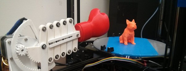
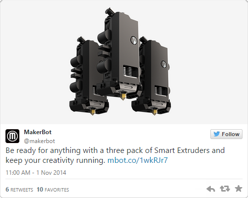
The phrase ‘meteoric rise’ doesn’t make sense, and since then the reputation of MakerBot has fallen through the floor, crashed through the basement, and is now lodged in one of the higher circles of hell. It’s not surprising; MakerBot took creations from their 3D object hosting site, Thingiverse, and patented them. The once-Open Source line of 3D printers was locked up behind a closed license. The new MakerBot extruder – the Smart Extruder – is so failure prone MakerBot offers a three pack, just so you’ll always have a replacement on hand. False comparisons to Apple abound; Apple contributes to Open Source projects. The only other way for a company to lose the support of the community built around it so quickly would be a name change to Puppy Kickers, LLC.

In the last few months, figurehead CEO of MakerBot [Bre Pettis] was released from contractual obligations, and MakerBot’s parent company, Stratasys, has filled the executive ranks with more traditional business types. It appears PR and Marketing managers have noticed the bile slung at their doorstep, and now MakerBot is reaching out to the community. Their new CEO, [Jonathan Jaglom] specifically requested a hot seat be built at Adafruit for an open discussion and listening meeting. Yes, this means Makerbot is trying to get back on track, winning the hearts and minds of potential customers, and addressing issues Internet forums repeat ad nauseam.

If you’ve ever wanted to ask a CEO how they plan to stop screwing things up, this is your chance. Adafruit is looking for some direction for their interview/listening meeting, and they’re asking the community for the most pressing issues facing the 3D printing community, the Open Source community, and MakerBot the company.

Already on the docket are questions about MakerBot and Open Source, MakerBot’s desire to put DRM in filament, the horrors of the Smart Extruder and the 5th generation MakerBots, problems with Thingiverse, and the general shitty way MakerBot treats its resellers.

This isn’t all Adafruit wants to ask; the gloves are off, nothing is off the table, and they’re looking for questions from the community. What would you like to ask the MakerBot CEO?

Personally, the best interview questions are when the interviewee’s own words are turned around on them. By [Jonathan Jaglom]’s own admission, the barrier to entry for 3D design work has been substantially lowered in the last three years, ostensibly because of incredible advances in Open Source projects. Following this, do MakerBot and Stratasys owe a debt to Open Source projects, and should Stratasys contribute to the rising tide of Open Source development?

That’s just one question. There will, of course, be many more. Leave them down in the comments. “You are not [Tim Cook],” while a valid statement in many respects, is not a question.

Automatic Print Ejector For All 3D Printers

Way back in 2010, Makerbot released the Automated Build Platform, a neat heated conveyor belt for the Cupcake or Thing-O-Matic that would spit parts out when a print was done. It’s a great invention if you need to produce 20 of something, and the perfect invention if you want to sit on a patent and not innovate anything ever.

You won’t need to wait until the year 2030 to get a device that automatically removes a print from a print bed. The folks at MatterHackers came up with an Automatic Print Ejector that removes a print in the most [Rube Goldberg]-ish way possible: with a boxing glove.

The Automatic Print Ejector is pretty much taken straight out of a [Buster Keaton] movie. It’s a series of scissor mechanisms with a 3D printed boxing glove on the end, driven by a stepper motor. When the print finishes, the boxing glove simply punches a print off the bed of a printer.

Does it work? It does, brilliantly. Check out the video below.

Continue reading “Automatic Print Ejector For All 3D Printers”

How To Build Beautiful Enclosures From FR4 — Aka PCBs

Most hobbyists say that it is easier to build a functional prototype of an electronic device, than to make the enclosure for it. You could say that there are a lot of ready-made enclosures on the market, but they are never exactly what you need. You could also use a 3D printer to build a custom enclosure, but high-end 3D printers are too expensive, and the cheaper ones produce housings which are often not robust enough, and also require a lot of additional treatment.

Another way is to build the enclosure out of FR4, a material which is commonly used in PCB production. Such enclosures are low-cost, with thin walls but yet very strong, nice looking, pleasant to the touch and have excellent thermal and moisture stability. FR4 offers some more possibilities – efficient wiring with no wires inside the housing, integrated UHF or SHF antennas or RFID coils, capacitive switches, electrical shielding, selective semi-transparency, water or air tightness, and even integration of complex mechanical assemblies.

Here I shall explain the process of building those “magic” enclosures. It is based on nearly fifty years of personal experience and more than a hundred enclosures, built for most of my projects. Here are two examples – this case for a hardware password manager is just a few centimeters long, while the other one (protective transportation cover for my son’s synthesizer) measures 125cm (about 49 inches), and yet both of them are strong enough to withstand a grown man standing on top of them.

The global approach is simple – you take the sheet of single-sided copper clad FR4, cut it and solder the parts together. That sounds simple, but there are a lot of details which should be met if you want to get top results. Please read about them carefully. You might be tempted to skip some of the steps described here, but if you do so, you will most likely end up being disappointed with the results.

Continue reading “How To Build Beautiful Enclosures From FR4 — Aka PCBs”