Look over any description of a water treatment plant, and you’ll find a description that includes the words, ‘coagulation tanks’. What are these treatment plants coagulating? You don’t want to know. How are they doing it? With chemicals and minerals. Obviously, there’s something else that can be done.
For their Hackaday Prize entry, [Ryan], [designbybeck], [Clint], [Wanda] and [Maker Mark] are investigating electrocoagulation. It’s an alternative to a frothy brew of chemicals that uses electricity to pull pollutants out of the water.
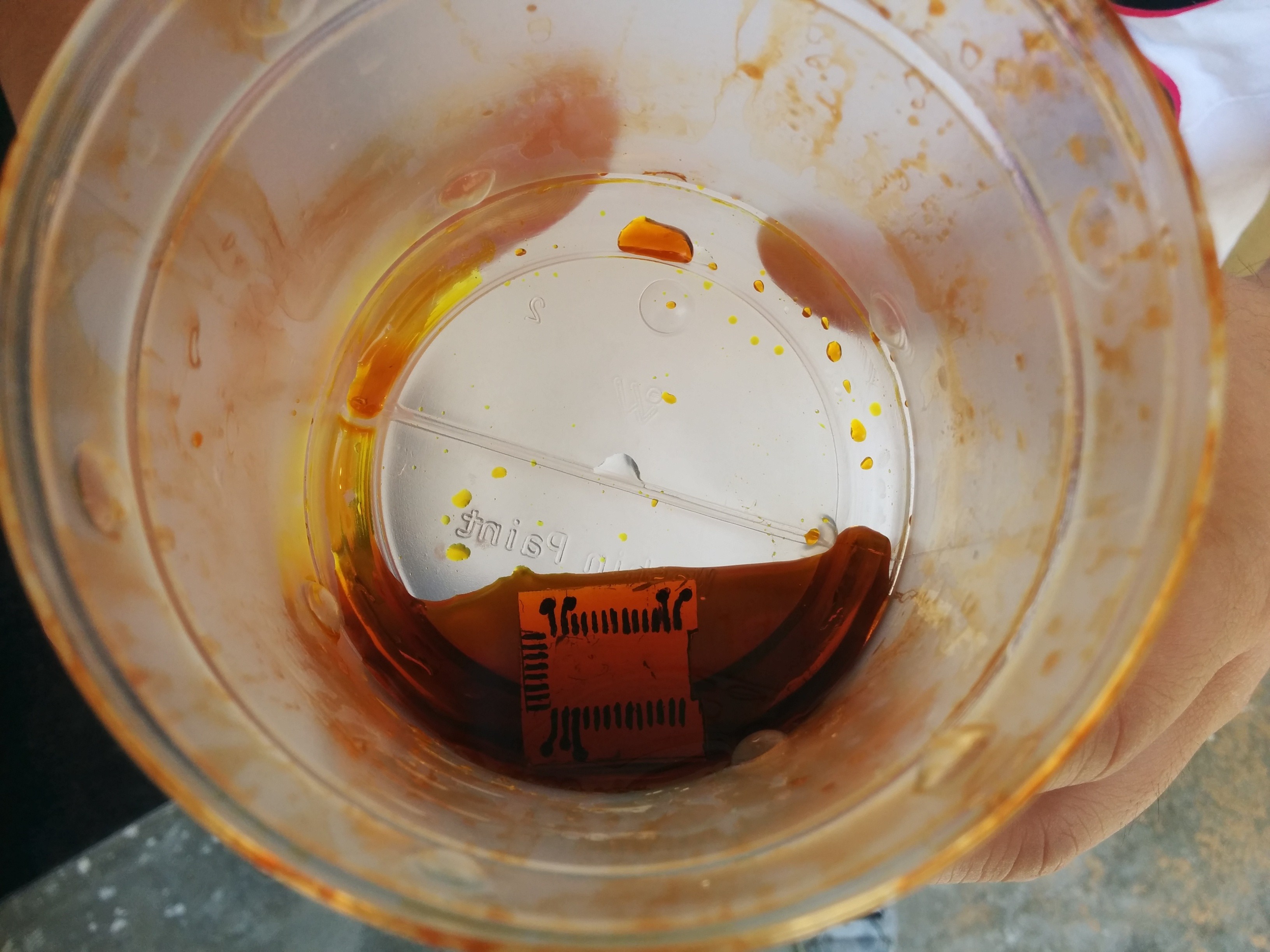
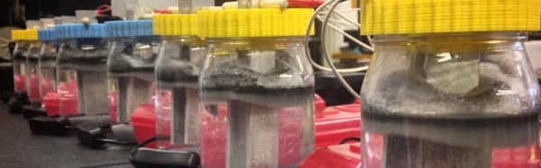
 Right now, the tests are much smaller in scale than the tens of thousands of gallons you’d find at a water treatment plant. In fact, the test rig is only a 16-ounce mason jar. While this isn’t large enough to precipitate pollutants out of a household water supply, it is big enough for a proof of concept.
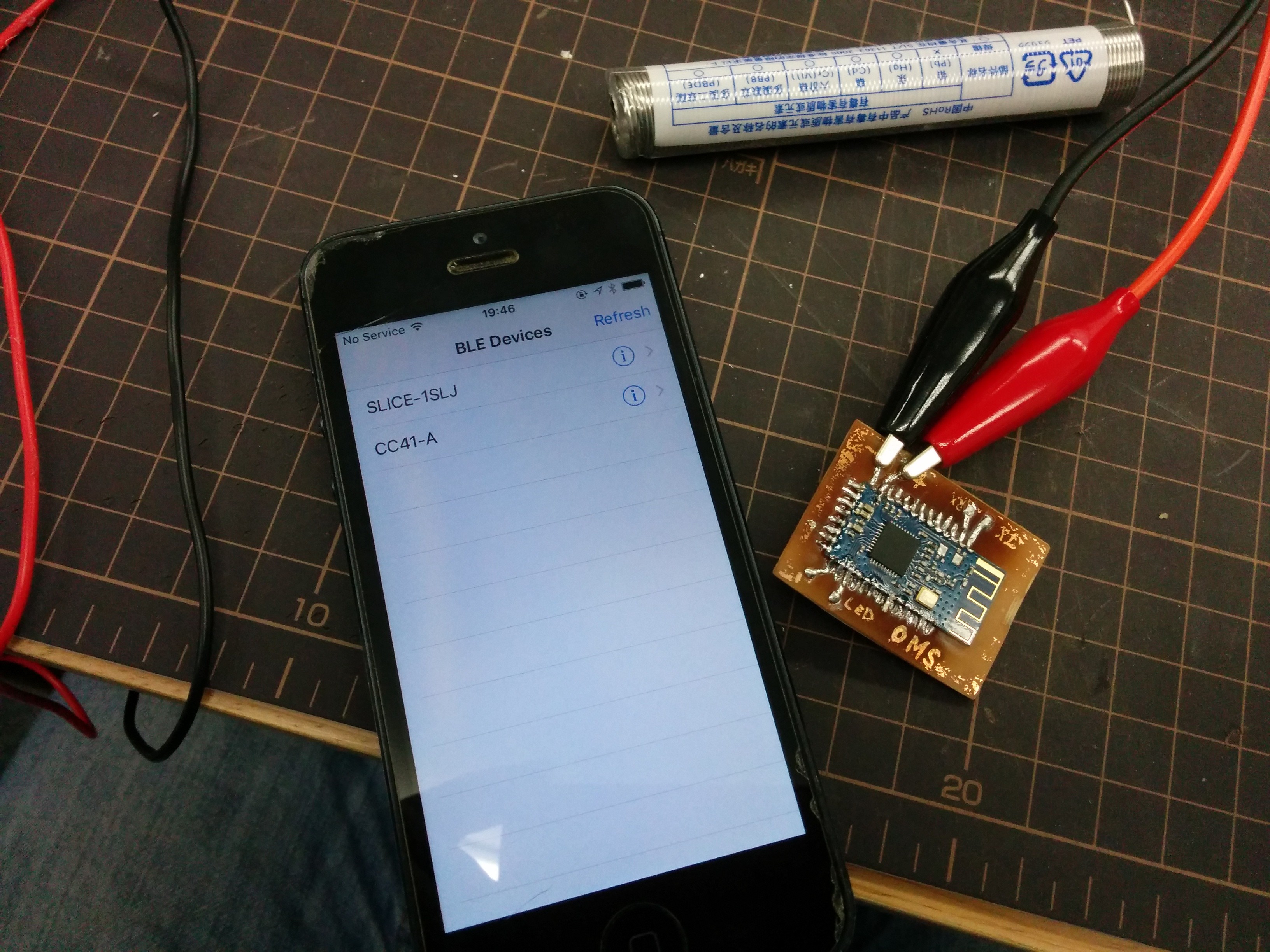
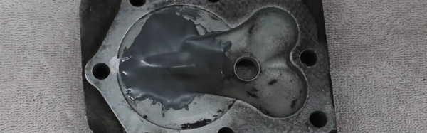
The team is using two electrodes for this build, one aluminum, and one iron. These electrodes are connected via alligator leads to the electronics board they’ve built. This electronics board is basically just an H-Bridge (used so they can reverse the polarity of the field emitter and prevent a buildup of gunk on the electrodes) and a few connectors to a power supply. The results are encouraging; they have a few time-lapse videos of a mason jar of dirty water clearing up with the power of electricity. It’s a great project with some great documentation. The team already has a bunch of updates on their project and instructions on how to replicate their hardware. You can check out those videos below.
Continue reading “Hackaday Prize Entry: Collaborative Water Purification”