The modern motorcycle represents the pinnacle of over a century of refinement in design and manufacture of its every component. A modest outlay will secure you a machine capable of three figure speeds with impeccable handling, breathtaking acceleration and stopping power, that somehow seems also to possess bulletproof reliability that will take it to a hundred thousand miles of faithful transport.
At the dawn of the internal combustion engine age it was a different matter. Machines were little more than bicycles with rudimentary engines attached, brakes and tyres were barely capable of doing the job demanded of them, and the early motorcyclists were a hardy and daring breed.
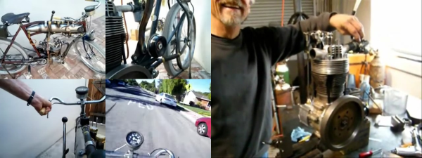
You might think that this article would now head into retrotechtacular territory with a nostalgic look at an early motorcycle, but instead its subject has a much more recent origin. We happened upon [Buddfab]’s contemporary build of a 1905-era motorcycle, and we think it’s a bike you’d all like to see.
The bike itself is a faithful reproduction of a typical Edwardian machine. It has a modified bicycle frame with a belt drive and springer front forks. That’s all very impressive, but the engine is a masterpiece, crafting a more modern parts bin into something resembling a 1905 original. He’s taken the cylinder, piston, and half a cylinder head from an aircooled VW flat four and mated it with the crankshaft of a 125cc Honda, welding the two connecting rods together to join German and Japanese parts. With a custom-made crankcase, Lucas points, and the carburetor from a British Seagull outboard motor it both looks and sounds like an original, though we’d expect it to be significantly more reliable.
You can see videos of both bike and engine below the break, as he takes it for a spin through American suburbia. Sadly we’ll never see it passed to the definitive writer on early motorcycles for an expert view, but it would fool us completely.
Continue reading “Motorcycling Like It’s 1905 With A Home Made Engine” →